Table of Contents
Advertisement
Quick Links
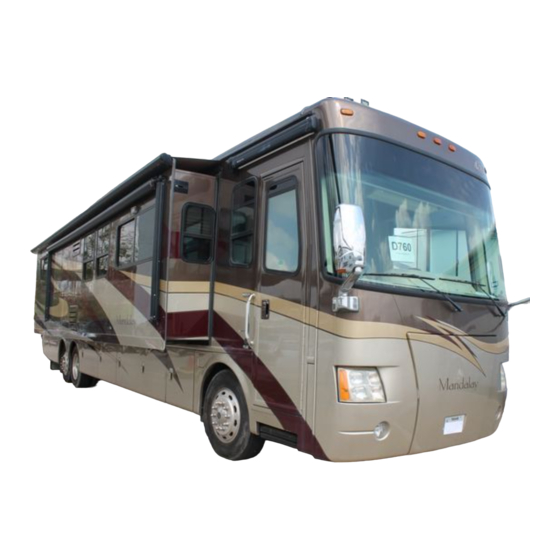
MANDALAY
01/2008
No part of this written material may be reproduced, in whole or in part, without the specific written permission of
Four Winds International Corporation. Unless otherwise provided therein, all written material is protected by
© copyright. To obtain permission to reprint text or images, please contact us: Technical Publications Department,
Four Winds International, P.O. Box 1486, Elkhart, IN 46515, Phone: 574-266-1111, Fax: 574-294-3618
MANDALAY
Advertisement
Table of Contents

Related Manuals for Thor Motor Coach 2009 Mandalay


Summary of Contents for Thor Motor Coach 2009 Mandalay
- Page 1 MANDALAY 01/2008 No part of this written material may be reproduced, in whole or in part, without the specific written permission of Four Winds International Corporation. Unless otherwise provided therein, all written material is protected by © copyright. To obtain permission to reprint text or images, please contact us: Technical Publications Department, Four Winds International, P.O.
- Page 2 MANDALAY...
-
Page 3: Table Of Contents
TABLE OF CONTENTS MANDALAY LIMITED WARRANTY MANDALAY LIMITED WARRANTY ............1-1 MANDALAY LIMITED WARRANTY ACKNOWLEDGEMENT OF RECEIPT . - Page 4 TABLE OF CONTENTS IDENTIFICATION & SAFETY CONTINUED... CHEMICAL SENSITIVITY .............3-15 Formaldehyde .
- Page 5 TABLE OF CONTENTS DASH CONTROLS & INSTRUMENT PANELS TRANSMISSION CONTROL PANEL ............5-1 AUTOMATIC HYDRAULIC POWER LEVELERS .
- Page 6 TABLE OF CONTENTS INTERIOR CONTROLS & OPERATIONS CONTINUED... FURNITURE ............... .6-8 Easy Bed Love Seat with Drawer (40E Only) .
- Page 7 TABLE OF CONTENTS HEATING & AIR CONDITIONING DASH PANEL HEATER/AIR CONDITIONER ..........8-1 Control Panel .
- Page 8 TABLE OF CONTENTS ELECTRICAL SYSTEMS CONTINUED... GENERATOR ..............9-19 Generator Maintenance .
- Page 9 TABLE OF CONTENTS CARE & MAINTENANCE EXTERIOR PAINT ..............12-1 Pressure Washing .
- Page 10 TABLE OF CONTENTS viii MANDALAY...
-
Page 11: Mandalay Limited Warranty
MANDALAY LIMITED WARRANTY WHAT THE PERIOD OF COVERAGE IS: This Limited Warranty provided by Mandalay® (“Warrantor”) covers those components, assemblies and systems of your new motorhome not excluded under the section “What is Not Covered”, when sold by a dealer authorized to sell the make/line of motorhome, for twelve (12) months from the first buyer’s retail purchase date or the first 15,000 miles of use, whichever occurs first. - Page 12 LIMITED WARRANTY WHAT WE WILL DO TO CORRECT PROBLEMS: Warrantor’s sole and exclusive obligation is to repair and/or replace, at its option, any covered defect if: (1) you notify Warrantor or one of its authorized servicing dealers of the defect within the warranty coverage period and within ten (10) days of discovering the defect;...
- Page 13 LIMITED WARRANTY WHAT THE WARRANTY DOES NOT COVER: This Limited Warranty does not cover: any motorhome sold or registered outside of the United States or Canada; items which are added or changed after the motorhome leaves Warrantor’s possession; items that are working as designed but with which you are unhappy with because of the design;...
- Page 14 LIMITED WARRANTY LEGAL REMEDIES: THIS LIMITED WARRANTY DOES NOT “EXTEND TO FUTURE PERFORMANCE”. ANY ACTION TO ENFORCE THIS LIMITED WARRANTY OR ANY IMPLIED WARRANTIES SHALL NOT BE COMMENCED MORE THAN 30 DAYS AFTER THE EXPIRATION OF THE WARRANTY COVERAGE PERIOD DESIGNATED ABOVE.
- Page 15 LIMITED WARRANTY Acknowledgement of Receipt of Warranty/Product Information IMPORTANT: The customer is required to read this document before signing it. We have listed several items which will help acquaint you with your new recreation vehicle. You the purchaser, should not submit this form until (1) you have received and reviewed the Limited Warranty and owner’s manual;...
- Page 16 LIMITED WARRANTY MANDALAY...
- Page 17 LIMITED WARRANTY COMPLETE THIS PRODUCT REGISTRATION CARD WITH THE SELLING DEALER AND RETURN WITHIN 10 (TEN) DAYS OF THE PURCHASE DATE MANDALAY...
- Page 18 LIMITED WARRANTY MANDALAY...
- Page 19 LIMITED WARRANTY COMPLETE THIS PRODUCT REGISTRATION CARD WITH THE SELLING DEALER AND KEEP IT FOR REFERENCE WHEN WARRANTY SERVICE IS REQUIRED MANDALAY...
- Page 20 LIMITED WARRANTY 1-10 MANDALAY...
- Page 21 LIMITED WARRANTY MANDALAY 1-11...
- Page 22 LIMITED WARRANTY 1-12 MANDALAY...
-
Page 23: General Information
GENERAL INFORMATION GENERAL INFORMATION SYMBOLS DANGER indicates an imminently hazardous situation which, if not avoided, will result in death or serious injury. WARNING indicates a potential hazardous situation which, if not avoided, could result in death or serious injury. CAUTION indicates a potentially hazardous situation which, if not avoided, may result in minor or moderate injury. -
Page 24: Introduction
INTRODUCTION INTRODUCTION It’s exciting taking ownership of a new purchase as substantial and full of nearly unlimited possibilities for the future as a motorhome. Thank you for choosing a Mandalay Luxury Division product. We take your choice seriously. That’s why we have engineered this vehicle to meet and, in many cases, exceed federal and state regulations and requirements for vehicles of this type. -
Page 25: Roadside Assistance Program
GENERAL INFORMATION This motorhome has been designed for short term recreational use. It is not intended to be used as a permanent dwelling or as a rental vehicle. If you intend to use the motorhome as a permanent dwelling or rental vehicle, it could cause the carpet, drapes, upholstery, and interior surfaces to deteriorate prematurely. -
Page 26: 24-Hour Customer Care Benefits
GENERAL INFORMATION 24-Hour Customer Care Benefits • Simply show your Thor Industries Customer Care Card for payment of covered benefits with no out-of-pocket expense throughout the U.S. and Canada. (Includes one additional family car!) • Toll-free nationwide service appointment assistance, the “no-hassle” way of getting a warranty service appointment when and where you travel. -
Page 27: Travel Preparation
GENERAL INFORMATION TRAVEL PREPARATION Chassis Checks Like any vacation trip, pre-planning will pay big dividends. In addition to routine trip preparations such as having newspaper delivery stopped and mail held at the post office, there are now more vehicle-related preparations than there are with an automobile. •... -
Page 28: Pre-Trip Checklist
GENERAL INFORMATION Pre-Trip Checklist Pay careful attention to where and what type of flammable materials you store. Certain storage areas are clearly labeled DO NOT STORE COMBUSTIBLE MATERIALS. Do not store flammable materials in areas which contain electrical systems such as the invertor and battery compartments. -
Page 29: Driving
GENERAL INFORMATION DRIVING The motorhome is equipped with more than adequate brakes; however, the stopping distance may be much greater than that of an automobile. Keep this in mind at all times, and be alert to changing road conditions. It would be helpful to take the motorhome to a large vacant parking lot and spend some time getting the feel of the wider and longer vehicle. - Page 30 GENERAL INFORMATION MANDALAY...
-
Page 31: Identification & Safety
IDENTIFICATION & SAFETY REPORTING SAFETY DEFECTS If you believe that your vehicle has a defect that could cause a crash or could cause injury or death, you should immediately inform the National Highway Traffic Safety Administration (NHTSA) in addition to notifying Mandalay Luxury Division. If NHTSA receives similar complaints, it may open an investigation, and if it finds that a safety defect exists in a group of vehicles, it may order a recall and remedy campaign. -
Page 32: Motorhome Serial Number Decal & Data Plates
IDENTIFICATION & SAFETY MOTORHOME SERIAL NUMBER DECAL & DATA PLATES The motorhome serial number label is mounted on the inside wall next to the driver seat. Refer to the chassis owner’s manual for the location of the chassis vehicle identification number on all motorized recreation vehicles. -
Page 33: Manufacturer's Warranties
IDENTIFICATION & SAFETY MANUFACTURER’S WARRANTIES The following list of components has been compiled to help you know which products within the motorhome may have their own warranties. If you have any of these components within the motorhome, be sure to check the literature supplied by the manufacturer to see if they require that you register your purchase with them to validate their warranty. -
Page 34: Safety Regulations For Propane Systems & Appliances
IDENTIFICATION & SAFETY SAFETY REGULATIONS FOR PROPANE SYSTEMS & APPLIANCES The following warnings are posted throughout the motorhome to provide information on Propane Gas safety. They have been installed not only because of the requirement to do so, but also as a constant reminder to occupants of the motorhome to exercise proper caution when using or being around Propane Gas appliances and equipment. -
Page 35: Propane System & Appliance Maintenance
IDENTIFICATION & SAFETY If you smell gas, extinguish any open flames, pilot lights, and all smoking materials. DO NOT touch electrical switches. Shut off the gas supply at the tank valve(s) or gas supply connection. Open doors and other ventilation openings. ( do not use the range hood ) Leave the area until the odor clears. -
Page 36: Fire Safety
IDENTIFICATION & SAFETY FIRE SAFETY Fire safety is an important part of owning a motorhome. Make sure that everyone traveling in the motorhome is familiar with the location of exits, including emergency exit windows should an emergency arise. The following basic rules of fire prevention can help eliminate the possibility of a fire. - Page 37 IDENTIFICATION & SAFETY The fire extinguisher, which is located by the entry door of the motorhome, is a chemical type suitable for extinguishing small fires of the class B or C type. Extinguishers are designed to put out fires in the initial stage, not when it is blazing out of control. If a fire cannot be approached within 10 feet, the extinguisher will not be effective.
-
Page 38: Carbon Monoxide & Smoke Detector
IDENTIFICATION & SAFETY CARBON MONOXIDE & SMOKE DETECTOR This Smoke/Carbon Monoxide Alarm cannot operate without two, AA batteries. Removing the batteries for any reason or failing to replace the batteries at the end of their service life, removes your protection. Refer to the manufacturers owner’s manual for proper replacement batteries. -
Page 39: Testing Procedure
IDENTIFICATION & SAFETY Testing Procedure DO NOT stand close to the alarm when the horn is sounding. Exposure at close range may be harmful to your hearing. When testing, step away when the horn starts sounding. Never use an open flame of any kind to test this unit. The built-in test switch accurately tests the unit’s operation as required by Underwriters Laboratories, Inc. -
Page 40: Carbon Monoxide Safety Precautions
IDENTIFICATION & SAFETY Carbon Monoxide Safety Precautions DO NOT alter or modify any component of the exhaust system at any time. Inspect the exhaust system at regular intervals for damage. If you suspect or locate damage to the system, have it repaired immediately by a qualified service facility. Never sleep while the engine or generator is running. -
Page 41: Propane Gas Detector
IDENTIFICATION & SAFETY PROPANE GAS DETECTOR The Propane Gas Leak Detector is powered at all times when the coach battery disconnect switch is in the ON position. When power is supplied to the detector, the green indicator light will illuminate. After 60 seconds, the detector will begin monitoring the air in the motorhome for combustible vapors. -
Page 42: How To Test
IDENTIFICATION & SAFETY How to Test Never use an open flame of any kind to test this unit. The built-in test switch accurately tests the unit’s operation as required by Underwriters Laboratories, Inc. (UL). Simply press the TEST switch any time during the warm-up cycle or while in normal operation. -
Page 43: About The Propane Gas Detector
IDENTIFICATION & SAFETY About the Propane Gas Detector Liquefied Petroleum Gas (Propane Gas) is heavier than air and will settle to the lowest point ,which is generally the floor of the coach. The detector is also sensitive to other fumes such as hair spray, of which most contain butane as the propellant. -
Page 44: Service
IDENTIFICATION & SAFETY NOTE: The Propane Gas Detector enters a cleaning and initializing mode every time it is powered. If turned OFF for less than 15 minutes, the Propane Gas Leak Detector may produce several short “chirps” within the first 80 seconds of operation. This is a normal function of the LP Gas Detector. -
Page 45: Chemical Sensitivity
IDENTIFICATION & SAFETY CHEMICAL SENSITIVITY After you first purchase your new motorhome and sometimes after it has been closed up for an extended period of time, you may notice a strong odor and chemical sensitivity. This is not a defect in your motorhome. Like your home, there are many different products used in the construction of motorhomes such as carpet, linoleum, plywood, insulation, upholstery, etc. -
Page 46: Seat Belts
IDENTIFICATION & SAFETY SEAT BELTS Do not occupy beds or any other seats that are not equipped with safety seat belts while the motorhome is in motion. Do not use a seat belt on more than one person. Pilot & co-pilot seats must be locked in a forward facing position with seat belts fastened while the motorhome is in motion. -
Page 47: Child Restraints
IDENTIFICATION & SAFETY Child Restraints Rear-facing child seats or infant carriers should never be placed in the front seats. Never let a passenger hold a child on his or her lap while the vehicle is moving. You are required by law to use safety restraints for children in the U.S. and Canada. If small children (generally children who are four years old or younger and who weigh 18 kg [40 lbs] or less) ride in your vehicle, you must put them in safety seats made especially for children. -
Page 48: Egress Window
IDENTIFICATION & SAFETY EGRESS WINDOW An egress window is designated for use as an exit in the case of an emergency. Inside the recreation vehicle the egress window is easily identified by the red locking handles. There are two common styles of latches, determine the style of locking handle you have and refer to the following illustrations for operation. -
Page 49: Chassis Operations & Procedures
CHASSIS OPERATIONS & PROCEDURES All issues regarding the Chassis Warranty, Parts & Service should be directed to : Freightliner Custom Chassis Corporation 552 Hyatt Street Gaffney, SC 29341 Customer Assistance Center: (800) 385-4357 The chassis is an integral part of the motorhome and with proper care and maintenance can provide many miles of reliable travel. -
Page 50: Tires
CHASSIS OPERATIONS & PROCEDURES TIRES Studies of tire safety show that maintaining proper tire pressure, observing tire and motorhome load limits (not carrying more weight in your motorhome than the tires or vehicle can safely handle), avoiding road hazards, and inspecting tires for cuts, slashes, and other irregularities are the most important things you can do to avoid tire failure, such as tread separation or blowout and flat tires. -
Page 51: Checking Tire Pressure
CHASSIS OPERATIONS & PROCEDURES Vehicle manufacturers determine this number based on the vehicle’s design load limit, that is, the greatest amount of weight a vehicle can safely carry and the vehicle’s tire size. The proper tire pressure for the motorhome is referred to as the “recommended cold inflation pressure.” (As you read below, it is difficult to obtain the recommended tire pressure if the tires are not cold.) Because tires are designed to be used on more than one type of vehicle, tire manufacturers list... -
Page 52: Tire Tread
CHASSIS OPERATIONS & PROCEDURES Tire Tread The tire tread provides the gripping action and traction that prevents the motorhome from slipping or sliding, especially when the road is wet or icy. A tread depth gauge is recommended to check your tread depth. Another simple way to check the tread depth of your tires is to use a penny. -
Page 53: Tire Rotation
CHASSIS OPERATIONS & PROCEDURES Tire Rotation The purpose of regularly rotating tire is to prolong their useful tire life by achieving more uniform wear for all tires on the motorhome. Before rotating tires, check the chassis owner’s manual for rotation recommendations for specific vehicles. If no rotation period is specified, speak with a qualified service technician or the tire manufacturer. -
Page 54: Tire Repair/Replacement
CHASSIS OPERATIONS & PROCEDURES Tire Repair/Replacement When replacing a tire, make sure that service personnel replace it with a tire of the same size and specifications. The proper repair of a punctured tire requires a plug for the hole and a patch for the area inside the tire that surrounds the puncture hole. -
Page 55: Tire Fundamentals
CHASSIS OPERATIONS & PROCEDURES Tire Fundamentals Federal law requires tire manufacturers to place standardized information on the sidewall of all tires. This information identifies and describes the fundamental characteristics of the tire and also provides a tire identification number for safety standard certification and in case of a recall. U.S. -
Page 56: Weight Terms
CHASSIS OPERATIONS & PROCEDURES Weight Terms The following is an explanation of commonly used weight abbreviations. • Gross Vehicle Weight Rating (GVWR) is the maximum permissible weight of this motorhome. • Unloaded Vehicle Weight (UVW) is the weight of this motorhome as manufactured at the factory with full fuel, engine oil, and coolants. -
Page 57: Cargo Capacities
CHASSIS OPERATIONS & PROCEDURES Cargo Capacities Cargo can be added to the motorhome, up to the maximum weight specified on the placard. For motorized vehicles, the combined weight of passengers and cargo is provided as a single number. If fewer people are traveling, more cargo can be added. If more people are involved, the weight of cargo must be reduced. -
Page 58: Tire Safety Tips
CHASSIS OPERATIONS & PROCEDURES Tire Safety Tips It is the air pressure that enables a tire to support the load, so proper inflation is critical. Since motorhomes can be configured and loaded in many ways, air pressures must be determined from actual loads (determined by weighing) and taken from the load and inflation tables provided by the tire manufacturer. -
Page 59: Trailer Towing
CHASSIS OPERATIONS & PROCEDURES TRAILER TOWING A separate functioning brake system is required for any towed vehicles or trailers weighing more than 1000 lbs when fully loaded. NEVER exceed the GVWR or the GAWR specified on the motorhome certification label. Also NEVER exceed the weight ratings of the trailer hitch installed on the motorhome. -
Page 60: Towing Procedures
CHASSIS OPERATIONS & PROCEDURES TOWING PROCEDURES Due to multiple variables that exist in towing the motorhome, operating/positioning the lifting and towing device is the sole responsibility of the tow vehicle operator. The operator must be familiar with standard towing industry safety measures. Improper procedures could result in personal injury or death. -
Page 61: Emergency Stopping
CHASSIS OPERATIONS & PROCEDURES If the motorhome needs to be towed: • Secure any loose or protruding parts if the motorhome is damaged. • Inspect the points of attachment on the disabled motorhome. If attachment points are damaged, select other attachment points at a substantial frame structural member. -
Page 62: Power Plant & Drive Train
CHASSIS OPERATIONS & PROCEDURES POWER PLANT & DRIVE TRAIN Full operating and service information may be obtained by consulting the engine and drive train operating and service manuals provided by the chassis manufacturer. For maximum engine efficiency and long service life, always follow recommendations as outlined by the chassis manufacturer. -
Page 63: Fueling The Motorhome
CHASSIS OPERATIONS & PROCEDURES FUELING THE MOTORHOME Be extremely careful when fueling the motorhome. Always shut off the engine. Do not smoke, or use cellular phones and shut off all pilot lights before adding fuel. Fuel spills represent a serious fire hazard and should be cleaned up immediately. Never restart the engine or relight pilot lights while raw fuel is present. - Page 64 CHASSIS OPERATIONS & PROCEDURES MANDALAY 4-16...
-
Page 65: Dash Controls & Instrument Panels
DASH CONTROLS & INSTRUMENT PANELS Thoroughly familiarize yourself with the various controls, instruments, and indicators located on the dash. Performance and safety can be enhanced by a driver who fully understands each one and how to use them. IMPORTANT: The following information is a quick reference guide for chassis functions and is not a replacement for the chassis owner’s manual. - Page 66 DASH CONTROLS & INSTRUMENT PANELS R (Reverse): Selection will display an “R”. This selection provides one range for backing the motorhome. N (Neutral): Selection will display an “N”. This selection shifts the transmission to Neutral. Neutral can be used to start the vehicle. If the transmission is in Neutral and the operator leaves the driver’s seat, the motorhome Parking Brake must be set to prevent the motorhome from rolling.
-
Page 67: Automatic Hydraulic Power Levelers
DASH CONTROLS & INSTRUMENT PANELS AUTOMATIC HYDRAULIC POWER LEVELERS With any hydraulic application, holding position on a cylinder must be done with safety in mind. Failure in the system may cause the leg(s) to retract or extend on its own. When working under or near the motorhome, always use jack stands of appropriate rating to support the weight of the motorhome. -
Page 68: Automatic Leveling & Retraction Procedure
DASH CONTROLS & INSTRUMENT PANELS Automatic Leveling & Retraction Procedure Make sure there are no obstructions in the extend or retract paths of the jacks. Keep all people clear of the motorhome while operating the leveling system. Do not allow excessive motion in the motorhome during the Auto-Level operation. This could cause the system to level improperly. -
Page 69: Manual Leveling & Retraction Procedure
DASH CONTROLS & INSTRUMENT PANELS Manual Leveling & Retraction Procedures Do not overextend the rear jacks. If the weight of the motorhome is removed from one or both rear wheels, the motorhome may roll forward or backward off of the leveling jacks. -
Page 70: Emergency Retraction Procedure
DASH CONTROLS & INSTRUMENT PANELS Emergency Retraction Procedure Following manual override operation, failure to return all valves to normal position may result in one or more jack legs drifting down from their retracted (stowed) position. For cartridge valves, rotate the center screw fully counter-clockwise. For directional valves, rotate the red knob until it ‘snaps’... - Page 71 DASH CONTROLS & INSTRUMENT PANELS HOSE COLOR IDENTIFICATION LOCATION EXTEND (T) RETRACT (B) JACK #1 (LEFT FRONT) Brown Brown/Black JACK #2 (RIGHT FRONT) White White/Black JACK #3 (LEFT REAR) Orange Orange/Black JACK #4 (RIGHT REAR) Yellow Yellow/Black MANDALAY...
-
Page 72: Shifter Panel Switches
DASH CONTROLS & INSTRUMENT PANELS SHIFTER PANEL SWITCHES Mirror Control Button: Used to adjust outside mirrors for visibility. Push the side selector left to adjust the roadside exterior mirror or right to adjust the curbside exterior mirror. Mirror Heat: Activates heating element to defrost the outside rearview mirrors. -
Page 73: Dash Panel Switches
DASH CONTROLS & INSTRUMENT PANELS DASH PANEL SWITCHES Block Heat: Activates the motorhome engine block heater (for use in cold weather). The block heater operates on 120 Volt AC provided by the generator or shore power. Docking Lights: Switches side docking lights on or off which are located on the rear wheel wells. -
Page 74: Passenger Armrest Switches
DASH CONTROLS & INSTRUMENT PANELS Gen Start/Prime/Stop: Depress and hold the top of the switch to start the generator. Depress the bottom of the switch to stop the generator. Depress and hold the bottom of the switch to prime the generator prior to starting. -
Page 75: Steering Wheel
DASH CONTROLS & INSTRUMENT PANELS STEERING WHEEL Smart Wheel Operation The smart wheel puts commonly used features at your fingertips. Those features include the Windshield Wiper Controls, Cruise Control & Headlamp Flash. REFERENCE: For detailed information regarding these buttons and their meanings, refer to the chassis manufacturer’s owner’s manual. -
Page 76: Turn Signal/Lane Change/High-Low Beam/Hazards Lever
DASH CONTROLS & INSTRUMENT PANELS Turn Signal/Lane Change/High-Low Beam/Hazards Lever The lever on the left side of the steering column controls the turn signal with lane change feature, as well as the Headlamp high/low beam toggle and the Hazard Lights. The turn signal lever has two off-center positions, one positions upward (for right) and one downward (for left). -
Page 77: Steering Wheel Adjustment
DASH CONTROLS & INSTRUMENT PANELS Steering Wheel Adjustment Tilt: • To tilt the steering wheel, depress the adjustment pedal (located at the base of the steering column) and move the steering wheel to where you want it. Release the pedal and the steering wheel will lock in the new position. Telescope: •... -
Page 78: Rear Vision System
DASH CONTROLS & INSTRUMENT PANELS REAR VISION SYSTEM Voyager System This system gives a televised view of what is behind the motorhome. It is used as an aid in backing the motorhome and can also be used for greater field of vision when driving in heavy traffic. -
Page 79: Pioneer System (Optional)
DASH CONTROLS & INSTRUMENT PANELS The color side view cameras help to alleviate blind spots during transit. The cameras are mounted within the exterior review mirrors. The corresponding side view camera image is displayed when a lane change or turn is signaled. To view the side view camera images with the Voyager system when not signaling a lane change or turn, depress the Select Button. -
Page 80: Gps Navigation System (Optional)
DASH CONTROLS & INSTRUMENT PANELS Use the camera system remote to adjust settings and other options. 1. Power Button: Press POWER button to turn the control box on or off. 2. -/+ Button: Press -/+ button to adjust BRIGHT or CONTRAST level. -
Page 81: Controls & Indicators
DASH CONTROLS & INSTRUMENT PANELS Controls & Indicators: 1. Disc Loading Slot 6. Volume Knob 2. Reset Button 7. Fast Forward Button 3. Eject Button 8. Backward Button 4. Menu Button 9. Mini Jack 5. Map Button A. LCD Display Basic Navigation Procedures 1. -
Page 82: Dash Radio
DASH CONTROLS & INSTRUMENT PANELS DASH RADIO The dash radio will control the multi-functions for the dash audio system. The tuner holds up to twelve preset FM channels, up to six AM channels, and up to six Satellite Channels (satellite service required). -
Page 83: Spotlight (Optional)
DASH CONTROLS & INSTRUMENT PANELS SPOTLIGHT (OPTIONAL) The spotlight mounted on top of the motorhome can be controlled by using the included remote. Using the remote control, turn on the light using the ON/OFF switch. With the four way switch on the remote control, adjust your light to the desired location. - Page 84 DASH CONTROLS & INSTRUMENT PANELS MANDALAY 5-20...
-
Page 85: Interior Controls & Operations
INTERIOR CONTROLS & OPERATIONS MONITOR PANEL Located above the entry door, the systems monitor panel provides quick and easy access to several different motorhome systems. (Panel shown with the Optional Oasis Heating Panel) NOTE: Refer to the “Electrical Systems” section for a detailed description of the Power Inverter Remote panel, as well as the Smart EMS panel. -
Page 86: Monitor Panel Switches
INTERIOR CONTROLS & OPERATIONS Inaccurate Holding Tank Level Readings: The accuracy of two wire holding tank monitoring systems can be adversely affected by dirty tanks, unusual mineral content in the water, or improper holding tank probe location. These conditions can cause the monitoring system to have oversensitive (read higher than actual level) or under sensitive (read lower than actual level) readings. -
Page 87: Slideouts
INTERIOR CONTROLS & OPERATIONS SLIDEOUTS Refer to the manufacturer’s operations manual for complete details and trouble shooting guide. Room Extension Procedure Operating the room with any room-locking device locked can cause personal injury and vehicle damage. It is the operator’s responsibility to ensure that all room-locking devices are disengaged before operating the room. -
Page 88: Room Retraction Procedure
INTERIOR CONTROLS & OPERATIONS To Extend: 1. Level the motorhome. 2. Ensure there is proper clearance to fully extend the slideout. 3. Apply the parking brake and activate the coach battery disconnect switch. 4. To extend the slideout, press and hold the ROOM CONTROL SWITCH in the “EXTEND”... -
Page 89: Manual Retraction Procedure
INTERIOR CONTROLS & OPERATIONS Manual Retraction Procedure Following manual override operation, failure to return all valves to normal position may result in slideout(s) creeping from their retracted (stowed) position. For cartridge valves, rotate the center screw fully counter-clockwise. For directional valves, rotate the red knob until it “snaps”... - Page 90 INTERIOR CONTROLS & OPERATIONS HOSE COLOR IDENTIFICATION LOCATION EXTEND RETRACT Slide 1 (Driver’s Side Front) Green Green/Black Slide 2 (Driver’s Side Rear) Purple Purple/Black Slide 3 (Passenger Side Front) Gray Gray/Black Slide 4 (Passenger Side Front) Red/Black MANDALAY...
-
Page 91: Windows
INTERIOR CONTROLS & OPERATIONS WINDOWS To avoid exhaust gas entry into the motorhome, keep windows closed when the chassis or generator engines are running. Windows that open in the motorhome are operated by sliding them back and forth or up and down, depending on the style and location of the window. -
Page 92: Furniture
INTERIOR CONTROLS & OPERATIONS FURNITURE Do not occupy beds or any other seats that are not equipped with safety seat belts while the motorhome is in motion. Do not use a seat belt on more than one person. Pilot & co-pilot seats must be locked in a forward facing position with seat belts fastened while the motorhome is in motion. -
Page 93: Magic Bed Sofa (40E, 40G, 43A, 43B & 43C)
INTERIOR CONTROLS & OPERATIONS Magic Bed Sofa (40E, 40G, 43A, 43B & 43C) Sofa to Sleeper: • Remove the back rest cushions. • Raise the sofa seat base until the seat base and backrest form a “V” shape by lifting up from the center of the sofa just below the seat cushions. -
Page 94: Recliner (Optional)
INTERIOR CONTROLS & OPERATIONS Recliner (Optional) The recliner operates just like a standard household recliner. By pulling the footrest lever, the footrest will extend. Since a seat belt is not provided on the recliner it is not to be used while in transit. -
Page 95: Bed Storage
INTERIOR CONTROLS & OPERATIONS Bed Storage Keep hands and fingers clear of the storage door edges while closing, to avoid pinch points. There is a large storage area located under the bed. It is accessed by first lifting the mattress up, then locate the pull strap and lift the storage door up. -
Page 96: Entertainment System
INTERIOR CONTROLS & OPERATIONS Using the Firmness Control System™: • The Firmness Control System™ is designed to make changes to one side at a time. When the Sleep Number® disappears from the wired remote display, changes may be made to the other side. •... -
Page 97: Video Selector Box
INTERIOR CONTROLS & OPERATIONS The TVs operate on 120V AC power. This power can be provided by shore power, the generator or the inverter. NOTE: Viewing time will be limited to the state of the house battery charge when using the inverter. -
Page 98: Dvd Receiver
INTERIOR CONTROLS & OPERATIONS Viewing Signals from Cable on Main TV: Press the Cable TV button above the area marked “Main TV”. Follow the same procedure for TV 2 and Exterior TV. Note: To view cable TV signals, you must be connected to a Cable TV input on the outside of the motorhome. -
Page 99: Television Antenna
INTERIOR CONTROLS & OPERATIONS Television Antenna Prior to raising the antenna, visually inspect for any obstructions or overhead electrical wires. Damage to the antenna, severe shock, personal injury or death can occur from inadequate clearance. Do not move the motorhome with the antenna in a raised or partially raised position. Damage to the antenna, the worm gear, or the motorhome roof may result. -
Page 100: Central Vacuum
INTERIOR CONTROLS & OPERATIONS CENTRAL VACUUM The central vacuum consists of the vacuum unit that is mounted in the kitchen base cabinet and a hose that will reach from the front to the rear of the coach. The hose simply plugs into the front of the unit after flipping up a small door. -
Page 101: Dishwasher (Optional)
INTERIOR CONTROLS & OPERATIONS DISHWASHER (OPTIONAL) Located in a kitchen base cabinet below the range top, the optional dishwasher is one of the many amenities offered for the Mandalay. The dishwasher is easy and quick to use and with the proper maintenance and care will provide many years of reliable service. - Page 102 INTERIOR CONTROLS & OPERATIONS MANDALAY 6-18...
-
Page 103: Exterior Operations
EXTERIOR OPERATIONS ENTRY DOOR The entry door is designed to provide security and comfort while traveling in the motorhome. The entry door utilizes three separate locks for these reasons. The first locking system is the door handle, the second is the independent deadbolt lock, the third lock is the automatic air lock. -
Page 104: Keyless Entry System
EXTERIOR OPERATIONS Keyless Entry System The entry door and cargo bay doors have been equipped with the e-ASK keyless-entry system. The system consists of two remote transmitter FOBs, an e-PAD keypad interface, and a dash toggle switch. The FOB transmitter and receiver are shipped pre-programmed. Only the unlocking function of the e-FOB remains while the engine is running - all other functions are disabled. -
Page 105: Assigning A New Authority Code
EXTERIOR OPERATIONS Default Access Code: DIGIT 1 DIGIT 2 DIGIT 3 DIGIT 4 DIGIT 5 Default Authority Code: DIGIT 1 DIGIT 2 DIGIT 3 DIGIT 4 DIGIT 5 Assigning a New Authority Code The Authority code should be changed upon purchase of your motorhome, for added security. Use the following steps to change the Authority code, also be sure write the new code in the area provided for reference later. -
Page 106: Assigning A New Access Codes
EXTERIOR OPERATIONS Assigning a New Access Codes With a valid authority code (see previous), an access code can be programmed with the following instructions. • Depress the 5/6 button, then release after the keypad provides a confirmation beep (approximately 5 seconds). The backlighting LED of the keypad will flash indicating the learn mode. -
Page 107: Power Entry Step
EXTERIOR OPERATIONS Power Entry Step Before exiting the motorhome, make sure that the step is activated and/or extended. Due to the height of the motorhome, you may accidentally slip or fall if attempting to exit without use of the step. If the step will not operate, use extra care when exiting. Never activate the step when someone is using it. -
Page 108: Storage Compartments
EXTERIOR OPERATIONS STORAGE COMPARTMENTS When closing the storage doors, make sure that hands and fingers are clear of pinch points. Make sure all compartment doors are completely closed, latched and contents are secure prior to moving the motorhome. To operate the compartment bay doors, unlock the latching mechanism using the compartment bay door key, the key FOB, or the keyless entry keypad. -
Page 109: Remote Air Fill
EXTERIOR OPERATIONS Remote Air Fill A convenient remote air fill has been placed within the front driver side compartment bay. Look toward the upper right corner of the compartment to locate the manifold with air lines attached to it. Plug the male end of the supplied air line into the quick connect coupler of the manifold, and turn on the valve to use. -
Page 110: Exterior Deep Freezer With Slideout Tray (Optional)
EXTERIOR OPERATIONS EXTERIOR DEEP FREEZER WITH SLIDEOUT TRAY (OPTIONAL) The deep freezer option consists of a freezer located in one of the curbside exterior storage compartments. The freezer is mounted on a slide that will allow you to pull it out for easy access. -
Page 111: Slideout Awning
EXTERIOR OPERATIONS NOTE: Removal of the awning from the motorhome requires more than one person. REFERENCE: For detailed information regarding the Entry Door Awning, refer to the A&E Systems, Oasis Automatic and Manual RV Door Awning System Installation & Operating Instructions Manual. - Page 112 EXTERIOR OPERATIONS Failure to strictly adhere to this retraction process may result in serius injury.. Manually Closing the Automatic Awning: • Two people will be needed to perform this procedure. • Slide the provided pull strap into the utility slot of the Fabric Roller Tube Assembly (FRTA).
-
Page 113: Bedroom Window Awning
EXTERIOR OPERATIONS Bedroom Window Awning To Extend: • Hook loop of pull strap with awning rod and pull awning, reel assembly and side arms to extend fully away from the motorhome. • Hook pull strap on side strap hook, remove the awning rod from pull strap and store. To Retract: •... -
Page 114: Rear Ladder/Roof Access
EXTERIOR OPERATIONS REAR LADDER/ROOF ACCESS Do not climb on or walk on the roof while wet. The roof could be very slippery causing you to fall, which can result in serious injury or death. Do not use the roof as an observation platform or storage area, as it is not designed for these purposes. -
Page 115: Heating & Air Conditioning
HEATING & AIR CONDITIONING DASH PANEL HEATER/AIR CONDITIONER The air conditioning system contains refrigerant 134a under high pressure and should be serviced by qualified personnel only. Improper service methods could cause serious personal injury. The motorhome is equipped with a high performance integrated heating/air conditioning system. -
Page 116: Operating Features
HEATING & AIR CONDITIONING Operating Features The air conditioning system is designed to operate in all modes except VENT, FLOOR and OFF. This provides significant moisture, dust and pollen removal for enhanced passenger comfort. Use MAX A/C and HI blower for quick cool down. A lower blower speed produces cooler air. To assist with cooling, close all windows and vents to hot, humid outside air. -
Page 117: Warranty/Service
HEATING & AIR CONDITIONING NOTE: The discharge air will heat up faster if the blower is operated on lower speeds until the engine is hot. For windshield de-icing, use DEFROST mode. Warranty/Service Keep the condenser and radiator free of bugs and debris. During periods of little use, operate the A/C system monthly to keep the compressor lubricated. -
Page 118: Return Air Filters
HEATING & AIR CONDITIONING Return Air Filters Do not use harsh chemicals or solvents to clean the filter. Clean the return air filters as needed for the environment in which they operate. The return air filters are inside the air intake vent covers located on the motorhome ceiling. Never operate the air conditioners without the return air filters in place. -
Page 119: Climate Control
HEATING & AIR CONDITIONING CLIMATE CONTROL The comfort control panel operates the individual components which together create the motorhomes HVAC (Heating, Ventilation, and Air Conditioner) system. NOTE: For a detailed description of how to operate and understand the climate control panel, refer to the Duo-Therm owner’s information. -
Page 120: Ceiling Vents
HEATING & AIR CONDITIONING CEILING VENTS Vents are provided in the motorhome to circulate fresh air and exhaust odors. Exhaust Vent The power vent has dual controls to operate both opening and closing, as well as the fan. A hand crank controls opening and closing and adjustment of the vent cover, while a push button turns the exhaust fan ON and OFF. -
Page 121: Vent Ceiling Fan With Rain Sensor
HEATING & AIR CONDITIONING Vent Ceiling Fan with Rain Sensor The vent ceiling fan with rain sensor is a three-speed fan which can extract air from the motorhome. The rain sensor provides added protection to the interior of the motorhome by clos- ing the vent dome when it starts to rain. - Page 122 HEATING & AIR CONDITIONING MANDALAY...
-
Page 123: Electrical Systems
ELECTRICAL SYSTEMS The electrical power supply provided for the motorhome is a dual operating system with 120 Volt AC and/or 12 Volt DC. The 120 Volt power may be provided by either connecting the motorhome to an outside power source when parked or by use of a motorhome generator. When the 120 Volt system is operational, power also passes through a system inverter allowing the full use of all 12 Volt functions in the motorhome. - Page 124 ELECTRICAL SYSTEMS A 50 amp shoreline power cord is provided to connect the motorhome to a grounded external power source. The shore cord is located in a compartment on the road side of the motorhome behind the rear wheels. There is a porthole in the bottom of the compartment to allow the power cord to be in use while leaving the storage compartment door closed.
-
Page 125: Shore Cord Power Reel
ELECTRICAL SYSTEMS Shore Cord Power Reel CAUTION: While retracting the power cord, keep hands clear of pinch points. The 50-amp power cord reel is located in a rear road side compartment bay. The power cord reel is a 12 Volt DC motorized assembly which will mechanically coil and stow the shore cord. The control switch actuates the reel to retract the power cord. -
Page 126: Ground Fault Circuit Interrupter (Gfci)
ELECTRICAL SYSTEMS Ground Fault Circuit Interrupter (GFCI) Even with the GFCI protection, persons with heart or other health problems may still be seriously affected by an electrical shock. The GFCI outlet is not a substitute for good electrical safety. It does not protect against contact of the hot and neutral wire at the same time. -
Page 127: Power Inverter
ELECTRICAL SYSTEMS POWER INVERTER The inverter takes 12 Volt DC from the house batteries and turns it into 120 Volt AC. It also takes 120 Volt AC when the motorhome is connected to shore power and transforms it into 12 Volt DC to recharge the house batteries. - Page 128 ELECTRICAL SYSTEMS Soft Keys: Press the soft keys to access the required function. Then use the rotary knob to scroll through the selections. Press the rotary knob to save the selection. Options include: • Shore Sets the appropriate breaker size for the incoming shore power and is used to control the amount of AC amps the battery charger uses from HOT 1 IN.
-
Page 129: Batteries
ELECTRICAL SYSTEMS BATTERIES The batteries for the motorhome are located on the passenger's side in a rear storage compartment designated for the batteries. It is important to make sure that the batteries are kept charged. Take time to turn off all lights or other 12 Volt functions when not in use. -
Page 130: Battery Maintenance
ELECTRICAL SYSTEMS Battery Maintenance Sulfuric acid in the batteries can cause severe injury or death. Sulfuric acid can cause permanent damage to eyes, burn skin and eat holes in clothing. Always wear splash-proof safety goggles and gloves when working around the battery. If battery electrolyte solution is splashed in the eyes or on the skin, immediately flush with clean water for 15 minutes. - Page 131 ELECTRICAL SYSTEMS • Repeat the process for each individual cell. The specific gravity reading should not have a difference of more that 30 "points" (0.030) between the lowest and highest reading or 10 "points" (0.010) below the battery manufacturer's recommended temperature value with the battery fully charged.
-
Page 132: Battery Charging
ELECTRICAL SYSTEMS Battery Charging If for any reason you charge a battery with a source outside the motorhome, make sure to follow the rules of battery maintenance and safety outlined in this section. Also observe these additional safety precautions related to battery charging. 1. -
Page 133: Battery Disconnect Switches
ELECTRICAL SYSTEMS Battery Disconnect Switches The battery disconnect switches allow you to easily disconnect the coach and chassis batteries from electrical circuits, preventing unwanted discharge during short periods of non-use. For long periods of non-use: Walk through the RV and manually shut off all 12 Volt powered items by their independent power switch. -
Page 134: Chassis Alternator
ELECTRICAL SYSTEMS Chassis Alternator The automotive chassis alternator supplies power to both the automotive systems as well as any coach battery. It also supplies power directly to the motorhome living quarters while the vehicle’s motor is running. The condition of the motorhome’s electrical system and especially the alternator, are of primary concern to you. -
Page 135: Solar Panel (Optional)
ELECTRICAL SYSTEMS SOLAR PANEL (OPTIONAL) The optional solar panel is mounted to the front A/C unit and is connected to the house batteries. The solar panel is designed to eliminate parasitic loads, such as monitor panel memory, on the batteries. It is not intended to fully charge the batteries. -
Page 136: Fuse Panels
ELECTRICAL SYSTEMS When connected to 240 Volt AC/50 Amp service or generator service, the Energy Management features of the unit are disabled and the unit switches all controlled loads "ON". It will not shed loads. If in either of these modes the load usage should require more than is present, you will trip the supply line breaker. -
Page 137: Volt Breaker Panel (40E, 40G, 7 40H)
ELECTRICAL SYSTEMS 120 Volt Breaker Panel (40E, 40G, & 40H) 120 Volt Breaker Panel (43A) 120 Volt Breaker Panel (43A with Optional Oasis Hydronic Heating) 120 Volt Breaker Panel (43B) MANDALAY 9-15... -
Page 138: Volt Breaker Panel (43B With Optional Oasis Hydronic Heating)
ELECTRICAL SYSTEMS 120 Volt Breaker Panel (43B with Optional Oasis Hydronic Heating) 120 Volt Breaker Panel (43C) 120 Volt Breaker Panel (43C with Optional Oasis Hydronic Heating/Dishwasher) 120 Volt Breaker Panel (43C with Optional Oasis Hydronic Heating/No Dishwasher) MANDALAY 9-16... -
Page 139: 12 Volt Fuse Panel
ELECTRICAL SYSTEMS 12 Volt Fuse Panel Dash Fuses The dash fuse panel is located under the dash on the wall. A circuit board with blade type fuses and breakers will be visible. The fuse and breaker locations are labeled below. MANDALAY 9-17... -
Page 140: Exterior 12 Volt Fuses
ELECTRICAL SYSTEMS Exterior 12 Volt Fuses The exterior 12 Volt systems fuse panel is located in the inverter compartment bay. The six slots might not all be used depending on equipped options. MANDALAY 9-18... -
Page 141: Generator
ELECTRICAL SYSTEMS GENERATOR Carbon monoxide is poisonous and can cause unconsciousness and death. Follow all instructions in this section as well as the ones outlined in the generator operation manual. IMPORTANT: Make sure to read and understand the generator owner’s manual before operating the generator. -
Page 142: Generator Maintenance
ELECTRICAL SYSTEMS 7. DO NOT simultaneously operate generator and a ventilator which could result in the entry of exhaust gas. 8. When parked, position the motorhome so that the wind will carry the exhaust away from the motorhome. DO NOT open nearby windows, ventilators, or doors into the passenger compartment, particularly those which can be “down wind”, even part of the time. -
Page 143: Water Systems
WATER SYSTEMS The motorhome plumbing system has the dual ability to be self-contained with on-board storage, or use facilities provided by an external pressurized source. In either case, the components of the system operate like those in your home. Components of the plumbing system consist of strong, lightweight, corrosion-resistance materials that provide long life and easy cleaning. -
Page 144: Water Pump
WATER SYSTEMS NOTE: There is an overflow line that will drain onto the ground if the tank is filled beyond capacity. Always fill the tank with potable water from a known safe source using a hose designated for potable water. Water Pump The self contained water system is a demand only system. -
Page 145: Hydronic Heating System (Optional 43A, 43B & 43C)
WATER SYSTEMS Hydronic Water Heating System (Optional 43A, 43B & 43C) The heating module uses a diesel burner (12 VDC) controlled by a multi-functional electronic controller as the primary source of heating coolant fluid (anti-freeze and water). Two 1500 Watt, 120 Volt AC immersion elements are used as secondary heat sources. -
Page 146: Sanitizing The Fresh Water System
WATER SYSTEMS Sanitizing the Fresh Water System Disinfecting the water system with chlorine bleach protects you and others from bacteriological or viral contamination from any common water source. The fresh water system should be disinfected prior to the first usage of the system, if the motorhome has not been used in a long time and once every three months. -
Page 147: Waste Water System
WATER SYSTEMS WASTE WATER SYSTEM The waste water system in the motorhome can be described as two separate systems. A gray water system that consists of drain lines and holding tank for waste water from the sink and tub, and a black water system which includes the holding tank and drain for toilet waste. In some cases the bathroom lavatory may drain into the black tank. -
Page 148: Emptying The Holding Tanks
WATER SYSTEMS Emptying the Holding Tanks 1. Remove the sewer drain hose from its storage compartment inside of the systems compartment. 2. Remove the cap from the vehicle sewage drain and connect the drain hose to it. 3. Attach the other end of the flexible drain line to the dump station inlet. Make sure both ends of the flexible drain lines are securely attached. -
Page 149: Toilet
WATER SYSTEMS Toilet The Thetford toilet installed in in the motorhome is connected to the pressurized fresh water system. There are two available flush modes controlled by the mode selector switch located at the back of the toilet. Up is user control/water saver mode and down is residential mode. For residential mode touch the large button once and walk away. -
Page 150: Water System Winterization
WATER SYSTEMS WATER SYSTEM WINTERIZATION If you intend to store the motorhome through periods of sub-freezing weather in an unheated environment, it will be necessary to winterize the water system. Damage to water system components will result if proper winterization steps are not taken. •... -
Page 151: Water System Maintenance & Troubleshooting
WATER SYSTEMS WATER SYSTEM MAINTENANCE & TROUBLESHOOTING As with any mechanical system, the plumbing is subject to development of problems. Most of these problems can be greatly reduced, if not altogether eliminated, by following a schedule of planned inspections and maintenance. Neglect of proper maintenance procedures is the usual cause of most water system problems. -
Page 152: Systems Compartment
WATER SYSTEMS SYSTEMS COMPARTMENT • Exterior Shower Provides hot or cold water to the exterior of the motorhome. • Cable/TV/Phone Jack Hook-up When available, provides cable and/or satellite to interior of motorhome. • 120 Volt Outlets • Water Heater Bypass Valve Diverts water flow around the water heater for winterization process. - Page 153 WATER SYSTEMS • Sewer Hose Storage Place the sewer hose here when not in use. • Fresh Water Tank Monitor Panel Check the fresh water tank level by pressing the level test switch. • Liquid Soap Dispenser Fill with soap for easy clean-up after working within the compartment. •...
- Page 154 WATER SYSTEMS MANDALAY 10-12...
-
Page 155: Propane Gas Systems
PROPANE GAS SYSTEMS Propane Gas is highly volatile and extremely explosive. Do not use matches or a flame to test for leaks. Use only approved Propane Gas leak testing solution for leak detection. Unapproved solutions can damage copper tubing and brass fittings. Never attempt to adjust Propane Gas regulators. -
Page 156: Propane Gas Tank
PROPANE GAS SYSTEMS PROPANE GAS TANK Filling the Propane Gas Tank Make sure that the tank is not filled beyond the 80% liquid level. Even though the tank is equipped with an automatic shut-off which prevents over-filling beyond 80% tank capacity, it is a good idea to have the supplier monitor the 20% liquid gauge and stop the filling process if liquid does appear. -
Page 157: Propane Gas Regulator
PROPANE GAS SYSTEMS PROPANE GAS REGULATOR Never alter the positioning of the regulator. Propane Gas regulators must always be installed with the diaphragm vent facing downward. Also make sure to keep the regulator cover in place to minimize vent blockage which could result in excessive gas pressure causing fire or explosion. -
Page 158: Regulator Freeze-Up
PROPANE GAS SYSTEMS During cold weather, it is important to keep ice from forming in the regulator, which will shut off the flow of Propane Gas to the appliances. Have the supplier add a hydrous Methanol when filling the tank for use during cold weather. Regulator freeze-up can occur in any weather if there is moisture in the tank or if the tank has been over-filled. -
Page 159: Hoses, Pipes, Tubes & Fittings
PROPANE GAS SYSTEMS NOTE: If freeze-up does occur, shut off the Propane Gas at the tank. A frozen regulator may permit Propane Gas to flow at high pressure, resulting in leaks at appliances or in the lines. If freeze-up does occur, NEVER attempt to thaw with an open flame. A small light bulb can sometimes be useful to provide heat and aid the thawing process. -
Page 160: Propane Gas Detector
PROPANE GAS SYSTEMS PROPANE GAS DETECTOR The Propane Gas Leak Detector is powered at all times when the coach battery disconnect switch is in the ON position. When power is supplied to the detector, the green indicator light will illuminate. After 60 seconds, the detector will begin monitoring the air in the motorhome for combustible vapors. -
Page 161: How To Test
PROPANE GAS SYSTEMS How to Test Never use an open flame of any kind to test this unit. The built-in test switch accurately tests the unit’s operation as required by Underwriters Laboratories, Inc. (UL). Simply press the TEST switch any time during the warm-up cycle or while in normal operation. -
Page 162: About The Propane Gas Detector
PROPANE GAS SYSTEMS About the Propane Gas Detector Liquefied Petroleum Gas (Propane Gas) is heavier than air and will settle to the lowest point which is generally the floor of the coach. The detector is also sensitive to other fumes such as hair spray of which most contain butane as the propellant. -
Page 163: Service
PROPANE GAS SYSTEMS Slow Beep Rate: This could be the failure alarm and will occur in the event that the circuitry fails. It is a continuous series of short beep tones between long intervals and is distinctively different from the alert sound. NOTE: After reviewing the above, if the problem still exists, contact MTI Industries for assistance. - Page 164 PROPANE GAS SYSTEMS MANDALAY 11-10...
-
Page 165: Exterior Paint
CARE & MAINTENANCE Periodic maintenance and cleaning of the motorhome is necessary to retain the dependability, safety, and appearance that will provide you with many miles of trouble free operation, as well as protecting your investment. Make sure to read and follow all the maintenance tips and schedules that appear in this manual. -
Page 166: Precautionary
CARE & MAINTENANCE Precautionary Measures Any exterior finish will deteriorate with time. Dulling and fading can be increased by prolonged exposure to extreme sunlight, air pollutants, and excessive moisture. Surface weathering of fiberglass will not diminish structural integrity. Regular monthly washing and polishing of exterior surfaces is the best insurance against surface deterioration such as fading, yellowing, or chalking. - Page 167 CARE & MAINTENANCE It is important to maintain the seals and adhesives of the motorhome to prevent moisture from entering and destroying the motorhome components. When washing the motorhome, inspect the seals for signs of dry rot and wear. Be aware that weather, sun, and road vibration will have an effect on seals, causing them to dry, crack, or separate.
-
Page 168: Extrusions & Aluminum Surfaces
CARE & MAINTENANCE EXTRUSIONS & ALUMINUM SURFACES Clean and wax all extrusions when waxing the motorhome sidewalls to help avoid surface pitting. Special aluminum cleaners are available to restore the original luster. Make sure to follow the instructions for use as outlined on the product package. Chrome surfaces can be restored with special chrome polish if regular cleaning methods are not successful. -
Page 169: Exterior Lights
CARE & MAINTENANCE Elevate the antenna and remove the set screw from the rotating gear housing (see illustration). Spray lubricant into hole and around the edges of the gear housing. Rotate the gear housing until the lubricant coats the bearing surfaces and the antenna rotates freely. -
Page 170: Pre-Finished Panels & Wood Surfaces
CARE & MAINTENANCE PRE-FINISHED PANELS & WOOD SURFACES Treat cabinetry and wood surfaces as you would any fine furniture product in your home. Proper care and maintenance of wood products will keep them looking like new for many seasons of use. Clean pre-finished panels with a spray-type furniture polish. -
Page 171: Abs Plastic
CARE & MAINTENANCE ABS PLASTIC Many components of the motorhome are constructed of strong, lightweight ABS plastic. Sometimes it may be necessary to remove stains or generally clean. A mild solution of soap and water will clean many stains and should be used initially. Tougher stains may require stronger cleaners, but be sure to read the label to determine if the product is recommended for use on plastics. -
Page 172: Propane Gas System
CARE & MAINTENANCE Propane Gas System WARNING: Never use the range for heating. Asphyxiation could result. Make sure to use a Propane Gas that will vaporize properly in the colder temperatures. Check with your Propane Gas representative for the proper fuel, and reread the information on Propane Gas selection in the “Propane Gas System”... -
Page 173: Frame
CARE & MAINTENANCE • Be sure that both the chassis and coach batteries have the proper electrolyte level and are fully charged (specific gravity of 1.260). A discharged battery will freeze and crack the case, ruining the battery. In storage, a battery will lose charge gradually over a 30 to 45 day period even when disconnected by use of the battery disconnect switch. -
Page 174: Mold
CARE & MAINTENANCE MOLD Molds are microscopic organisms that naturally occur in virtually every environment, indoors and out. Outdoors, mold growth is important in the decomposition of plants. Indoors, mold growth is unfavorable. Left unchecked, molds break down natural materials, such as wood products and fabric. -
Page 175: Effects Of Prolonged Occupancy
CARE & MAINTENANCE Effects of Prolonged Occupancy Your motorhome was designed primarily for recreational use and short-term occupancy. If you expect to occupy the motorhome for an extended period, be prepared to deal with condensation and the humid conditions that may be encountered. The relatively small volume and tight compact construction of modern motorhomes mean that the normal living activities of even a few occupants will lead to rapid moisture saturation of the air contained in the motorhome and the appearance of visible moisture, especially in cold weather. -
Page 176: Avoid Drastic Thermostat Setbacks
CARE & MAINTENANCE • The natural tendency would be to close the vehicle tightly during cold weather. This will actually compound the problem. Simply put, you need to remove some of the warm air, and allow some cool outside air to get inside the vehicle, so the furnace will not recycle the humid interior air. -
Page 177: Storage Of The Motorhome
CARE & MAINTENANCE Storage of the Motorhome During those periods when the motorhome is not in use, care must be taken to ensure moisture sources are addressed. Ideal storage of the motorhome would be in an enclosed climate controlled environment. When this is not possible, the following steps should be taken to ensure moisture is controlled: •... -
Page 178: Periodic Maintenance Chart
CARE & MAINTENANCE PERIODIC MAINTENANCE CHART For your convenience, a Maintenance Chart is presented below. For detailed information regarding specific product service and maintenance procedures, refer to the products respective owner’s manual. NOTE: The following chart is a guide only. Service and maintenance intervals may vary depending on product performance, usage, and/or environmental conditions. -
Page 179: Vendor Contact Information
CARE & MAINTENANCE VENDOR CONTACT INFORMATION ASA Electronics First Alert 53200 Marina Drive 3901 Liberty Street Road Elkhart, IN 46514 Aurora, IL 60504 800-688-3135 800-323-9005 www.asaelectronics.com www.firstalert.com Atwood Mobile Products, Inc. Flexsteel Industries 4750 Hiawatha Drive 72104 County Road 23 Rockford, IL 61103 New Paris, IN 46553 800-825-4328... - Page 180 CARE & MAINTENANCE KVH Industries, Inc. Norcold 50 Enterprise Center 2655 Cambell Road Middletown, RI 02842 Sidney, OH 45365 401-847-3327 800-543-1219 www.kvh.com www.norcold.com Kwikee Products Co. Inc. Onan 230 Davidson Avenue 1400 73rd Avenue NE Cottage Grove, OR 97427 Minneapolis, MN 55432 800-736-9961 800-888-6626 www.kwikee.com...
- Page 181 CARE & MAINTENANCE Thetford 2655 Cambell Road Sidney, OH 45365 800-521-3032 www.thetford.com TriMark Corp. 510 Bailey Avenue New Hampton, IA 50659 800-431-8616 www.trimarkcorp.com Velvac 2405 S Calhoun Road New Berlin, WI 53151 800-783-8871 www.velvac.com Viracon 500 Park Drive Owatonna, MN 55060 800-533-0482 www.viracon-autoglass.com Visteon Corp.
- Page 182 CARE & MAINTENANCE MANDALAY 12-18...
-
Page 183: Index
INDEX ABS Plastic ......... . .12-7 Appliances, Sinks &... - Page 184 INDEX Dash Panel Heater/Air Conditioner ......8-1 Air Distribution - Mode Control .......8-2 Control Panel .
- Page 185 INDEX Exterior Paint ......... .12-1 Precautionary Measures .
- Page 186 INDEX Fuse Panels ......... . .9-14 12 Volt Fuse Panel .
- Page 187 INDEX Mandalay Limited Warranty .......1-1 Mandalay Limited Warranty Acknowledgement of Receipt ..1-5 Mandalay Limited Warranty Transfer Application .
- Page 188 INDEX Propane Gas Detector ......3-11, 11-6 About the Propane Gas Detector ......3-13, 11-8 Checking the Propane Gas System for Leaks .
- Page 189 INDEX Slideouts ..........6-3 Manual Retraction Procedure .
- Page 190 INDEX Travel Preparation ........2-5 Chassis Checks .
Need help?
Do you have a question about the 2009 Mandalay and is the answer not in the manual?
Questions and answers