Table of Contents
Advertisement
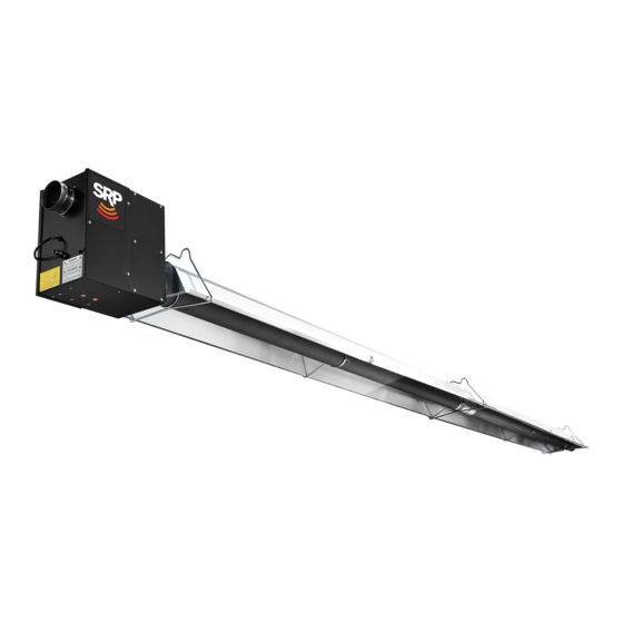
Series UA/UX/UXR Infrared Heater
Installation, Operation and Service Instructions
FOR YOUR SAFETY
If you smell gas:
1. Open windows
2. Don't touch electrical switches
3. Extinguish any open flame
4. Immediately call your gas supplier
CONSIGNES DE SECURITE
Si vous sentez une odeur de gaz:
1. Ouvrez les fenetres
2. Ne touchez pas aux interupteurs
electriques
3. Eteignez tout flamme nue
4. Contactez immediatment votre
fournisseur de gaz
Read and thoroughly understand these Instructions before attempting any installation.
Improper installation, adjustment, alteration, service or maintenance can cause injury, death or property
damage. Read the installation, operation and service instructions thoroughly before installing or servicing
Series UA/UX/UXR
Installer
Retain this Manual for reference.
WARNING
this equipment.
563 Barton Street, Stoney Creek, Ontario L8E 5S1
www.superiorradiant.com
FOR YOUR SAFETY
Do not store or use gasoline or other
flammable vapors and liquids in the
vicinity of this or any other appliance.
CONSIGNES DE SECURITE
Il est interdit d'utiliser des liquides
inflammables ou degageant des vapeurs
inflammables, a proximites de tout appareil
fonctionnent au gaz.
Owner
Page 1
Feb18/2015 LT011
Advertisement
Table of Contents
Troubleshooting


Need help?
Do you have a question about the UA Series and is the answer not in the manual?
Questions and answers