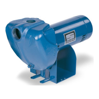
Pentair STA-RITE DS3 Series Owner's Manual
Self-priming centrifugal pump
Hide thumbs
Also See for STA-RITE DS3 Series:
- Installation and operation manual (13 pages) ,
- Owner's manual (90 pages) ,
- Owner's manual (12 pages)
Advertisement
OWNER'S MANUAL
Self-Priming Centrifugal Pump
"DS3" Series
3621 0714 ASB
Installation/Operation/Parts
For further operating, installation,
or maintenance assistance:
Call 888-782-7483
293 WRIGHT STREET, DELAVAN, WI 53115 WWW.STA-RITE.COM
PH: 888-782-7483
S536 (07/07/14)
© 2014 Pentair Ltd. All Rights Reserved.
Advertisement
Table of Contents

Subscribe to Our Youtube Channel
Summary of Contents for Pentair STA-RITE DS3 Series
- Page 1 OWNER’S MANUAL Self-Priming Centrifugal Pump “DS3” Series 3621 0714 ASB Installation/Operation/Parts For further operating, installation, or maintenance assistance: Call 888-782-7483 293 WRIGHT STREET, DELAVAN, WI 53115 WWW.STA-RITE.COM PH: 888-782-7483 S536 (07/07/14) © 2014 Pentair Ltd. All Rights Reserved.
-
Page 2: Safety
Safety READ AND FOLLOW GENERAL SAFETY SAFETY INSTRUCTIONS! WARNING This is the safety alert symbol. When you see this symbol on your pump or in this manual, look for one of Hazardous pressure! the following signal words and be alert to the potential Install pressure relief valve in discharge pipe. -
Page 3: Table Of Contents
Table of Contents Thank you for purchasing a top quality, factory tested pump. Page Safety ........................2 Warranty......................3 Installation ......................4-5 Electrical ......................6 Operation ......................7 Maintenance ....................8-10 Troubleshooting ....................11 Repair Parts ......................12 Limited Warranty STA-RITE warrants to the original consumer purchaser (“Purchaser” or “You”) of the products listed below, that they will be free from defects in material and workmanship for the Warranty Period shown below. -
Page 4: Warranty
Installation BEFORE YOU INSTALL YOUR PUMP Priming plug NOTICE: Well must not be more than 20’ depth to water. 1. Long runs and many fittings increase friction and reduce flow. Locate Priming tee pump as close to well as possible: use as few elbows and fittings as Suction possible. -
Page 5: Installation
Installation HORIZONTAL PIPING FROM WELL TO PUMP 1. Never install a suction pipe that is smaller than the suction port of the pump. 1 0 0 2. To aid priming on well point installations, install a line check valve as shown in Figure 2. Be sure check valve flow arrow points toward pump. -
Page 6: Electrical
Electrical Connection diagram for dual voltage, single-phase 5. Attach the ground wire to the green ground screw motors. Your dual-voltage motor’s terminal board (under 6. Reinstall the Motor end cover the motor end cover) will match one of the diagrams Go to Wiring Connections below. -
Page 7: Operation
Electrical / Operation Wiring Chart – Recommended Wire and Fuse Sizes DISTANCE IN FEET(METERS) FROM MOTOR TO SUPPLY 0 - 50 51 - 100 101 - 200 201 - 300 (0 - 15) (31 - 61) (62 - 91) (92 - 122) Max. -
Page 8: Pump Disassembly
Maintenance 3. Fill pump and suction pipe with water. 4. Replace priming plug, using PTFE pipe thread sealant tape on thread; tighten plug. NOTICE: If a priming tee and plug have been provided for a long horizontal run, be sure to fill suction pipe through this tee and replace plug. -
Page 9: Maintenance
Maintenance 4. Unscrew capacitor clamp and remove capacitor. Do not disconnect capacitor wires to motor. 5. Slide 7/16” open end wrench in behind spring loaded switch on motor end of shaft; hold motor shaft with wrench on shaft flats and unscrew impeller screw (if used) by turning clockwise (left hand thread) when looking into eye of impeller. - Page 10 Maintenance 10. Hold motor shaft with 7/16” open end wrench on shaft flats and screw impeller onto shaft. Be sure you do not touch capacitor terminals with body or any metal object. Tightening impeller will automatically locate seal in correct position. 11.
-
Page 11: Troubleshooting
Troubleshooting SYMPTOM POSSIBLE CAUSE(S) CORRECTIVE ACTION Motor will not run Disconnect switch is off Be sure switch is on Fuse is blown Replace fuse Starting switch is defective Replace starting switch Wires at motor are loose, Refer to instructions on wiring. Check and tighten all wiring. disconnected, or wired incorrectly Capacitor voltage may be hazardous. -
Page 12: Repair Parts
Repair Parts 3621 1199SPC MODEL NUMBER DS3HE-01 DS3HF-01 DS3HG-01 DS3HHG-01 Part DS3HE3-01 DS3HF3-01 DS3HG3-01 DS3HHG3-01 Description Qty. 1 HP 1-1/2 HP 2 HP 2-1/2 HP Motor, 115/230V, 1 Phase J218-596PKG J218-601PKG J218-883APKG J218-628A Motor, 230/460V, 3 Phase AP100EL AP100FL AP100GL AP100G5L Water Slinger 17351-0009...


Need help?
Do you have a question about the STA-RITE DS3 Series and is the answer not in the manual?
Questions and answers