
Related Manuals for Pentair MYERS DP Series


Summary of Contents for Pentair MYERS DP Series
- Page 1 INSTALLATION AND SERVICE MANUAL NOTE! To the installer: Please make sure you provide this manual to the owner of the equip ment or to the responsible party who maintains the system. Part # 23833A148 | © 2012 Pentair Ltd. | 12/05/12...
- Page 2 (kg) (95.25) (76.20) (38.10) (41.3) (9.53 x 4.76) (328.8) 1⅟Bore ¾ x ¾ K.W. * Belts – Matched Sets of (4) 5V 1000 (100" Outside Circumference), 30.4" Center Distance ® Steel/Babbitt Inserts Recommended Pressure Regulator Recommended Pulsation Dampener ENG. NO. ENG.
-
Page 3: Suggested Maintenance Schedule
INSTRUCTIONS 5. Fill tank at least half full or connect suction to water supply. Open valve (if present) in suction CAUTION: Positive Displacement Pumps must line. Avoid prolonged dry operation which may have a proper size and operable type of pressure cause excessive wear on plunger packing. - Page 4 ADDITIVES FOR CRANKCASE OIL Use of Molybdenum Disulfide (MoS ) is recommended by Myers as an additive to non-synthetic oil in back geared pumps manufactured by Myers. The additive is compatible with all known oils. It is so effective in reducing wear and friction that power train life may be doubled between overhauls.
- Page 5 grab only Place packing spring (59); check O-ring and backup ring in valve cap (51). Replace if you see any sign of wear. valve Using Kit 19555B1, assemble stud, retainer and three LARGE screws as shown in Fig. 2. Insert screw heads through holes in valve seat, rotate "...
- Page 6 and replace if Figure 5 shows a recommended thimble for seat, being Nylock C. Inspect O-rings and backup rings on valve caps (51). Replace if O-rings show signs of wear or nibbling. Lubricate O-rings and replace valve cap. Torque valve cap until it stops. CAUTION – Do not use a hand or arbor press to IMPORTANT – Note the markings on the connecting (See Fig. 6.) . Remove from gear case by moving and unscrewing and pushing ceramic plunger toward 23833A148 12/05/12...
- Page 7 the center of the pump as shown. .015 thick and gauge in a manner as shown in Fig. 7. (.005 – .009) has been added approximately .030 shim, and tighten the four cap screws to recommended torque. requires that correct shaft end play ensures that lbs. axial force to properly seat tapered rollers. Measure end play by using an indicating gauge in a manner shown in Fig.7. ensure that the (.005 – .009) driven pumps. hand-press " as indicated in draw- ⅟ 23833A148 12/05/12...
- Page 8 end first), then push both bearing caps into place. 3.1240 – 3.1245". Contact Engineering Department and tighten the five cap screws. refit connecting link. Always be sure that the proper side of the link is placed upward when attaching it to the crankshaft. The upper side contains an oil 1.125 – 1.126 Install the left cap without shims and secure with two cap screws positioned exactly as shown in Fig. 8. Torque the two cap screws at 13 foot- pounds, rotate the crankshaft, and retorque the cap screws. Do this three times to properly seat the...
- Page 9 23833A148 12/05/12...
- Page 10 , in some cases, it will 23833A148 12/05/12...
- Page 11 , will not operate satisfactorily or quietly bypassed and recirculated back lubrication instructions. can be detected only by visual examination of are drawn , disrupting 23833A148 12/05/12...
- Page 12 Drain bypass line by disconnecting or if there is a drain point, remove plug. This will become evident only after the rod ensure valves do not frost to and check for 23833A148 12/05/12...
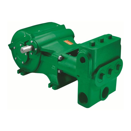
- Page 13 O-ring O-ring, 1 10-000110-201 9*** 27938B020 20164B022A 19101A009 27937C022 19*** 27937C044 05674A021 O-ring, * New part for DP Power End ** L.H. = Left-Hand Drive and R.H. = Right-Hand Drive Picture on cover of these instructions illustrates right-hand drive pump. ***NOTE: When purchasing the crankshaft or pinion on units built prior to 07/12, both items will need to be replaced due to an improvement in design. 23833A148 12/05/12...
- Page 14 fluid end fluid end fluid end (after August, 1996) fluid end models valve models except valve models O-ring models backup models models ® suction valve models (after August, 1996) discharge valve models (after August, 1996) suction valve models models discharge valve spring models cap, thrd. lock models packing packing packing...
- Page 15 (After 13 August, 1996) Backup O-ring O-ring Backup fluid end (after 13 August, 1996) models valve, discharge backup models models O-ring valve, suction (after 13 August, 1996) O-ring (after 13 August, 1996) (after 13 August, 1996) backup suction valve (after 13 August, 1996) discharge valve (after 13 August, 1996) spring...
- Page 16 Item Qty. Part No. Description 04625E100 Case, gear 27938B040 Shaft, pinion 05863A024 Shim, green, .003 Thk. 05863A023 Shim, pink, .015 Thk. 05674A020 Cone, bearing 05675A019 Cup, bearing 04741B010 Cap, bearing & seal 05710A046 Seal, oil 17272A013 Protector, plastic 06106A048 Screw, cap, socket head Grade 8 5/16-24UNF x 1"...
- Page 17 23833A148 12/05/12...
- Page 18 THIS PAGE INTENTIONALLY LEFT BLANK...
- Page 19 THIS PAGE INTENTIONALLY LEFT BLANK...
- Page 20 (f) if unit is used for purposes other than for what it is designed and manufactured; (g) to any unit that has been repaired or altered by anyone other than Pentair Myers or an authorized Pentair Myers service provider;...
Need help?
Do you have a question about the MYERS DP Series and is the answer not in the manual?
Questions and answers