Pentair STA-RITE DS3 Series Installation And Operation Manual
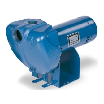
Self-priming centrifugal pump
Hide thumbs
Also See for STA-RITE DS3 Series:
- Owner's manual (12 pages) ,
- Owner's manual (90 pages) ,
- Owner's manual (12 pages)

Related Manuals for Pentair STA-RITE DS3 Series


Summary of Contents for Pentair STA-RITE DS3 Series
- Page 1 SELF-PRIMING CENTRIFUGAL PUMP DS3 SERIES 3621 0714 ASB INSTALLATION AND OPERATION MANUAL pentair.com/sta-rite...
-
Page 2: Table Of Contents
TABLE OF CONTENTS SECTION ........................................PAGE Safety ........................................3 Installation ......................................4-5 Electrical ........................................6 Operation ........................................7 Maintenance ......................................8-10 Troubleshooting ...................................... 11 Parts List .........................................12 Limited Warranty .....................................13 S536 (11-25-19) -
Page 3: Safety
SAFETY Carefully read and follow all safety instructions in this manual GENERAL SAFETY or on pump. This is the safety alert symbol. When you see this symbol on your pump or in this manual, look for one of the following signal words and be alert to the potential for personal injury. -
Page 4: Installation
INSTALLATION PRIOR TO PUMP INSTALLATION Priming plug Prior to pump installation, follow these steps to ensure proper Priming tee installation and operations. Suction pipe 1. Well must not be more than 20’ depth to water. 2. Be sure well is clear of sand. Sand will plug the pump and void the Standing water level (pump off) warranty. - Page 5 INSTALLATION DISCHARGE PIPE SIZES PUMP INSTALLATION 1. If increasing discharge pipe size, install reducer in pump discharge 1. Install pump as close to well head as poss ible. Long piping runs port. Do not increase pipe size by stages. and many fittings create friction and reduce flow. 2.
-
Page 6: Electrical
ELECTRICAL Hazardous voltage. Can shock, burn, or cause death. Ground Disconnect power to motor before working on pump or motor. Screw Ground motor before connecting to electrical power Voltage Change supply. Failure to ground motor can cause severe or fatal electrical Plug shock hazard. - Page 7 ELECTRICAL 3. Ground the pump permanently using a wire of the same size as that specified in this section’s Wiring Chart. Make ground connection to green grounding terminal under motor canopy marked GRD. or 4. Connect ground wire to a grounded lead in the service panel or to a metal underground water pipe or well casing at least 10 feet long.
-
Page 8: Operation
OPERATIONS/MAINTENANCE PRIMING THE PUMP B. When priming, monitor pump and piping tempera ture. If pump or piping begin to feel warm to the touch, shut off pump and allow ‘Priming’ refers to the pump expelling all air in the system and system to cool off. -
Page 9: Maintenance
MAINTENANCE MAINTENANCE Pump and piping need not be disconnected to repair or replace motor or seal (Figure 10). If motor is replaced, replace the shaft seal (see Parts List). Keep one on hand for future use. Be sure to prime pump before starting. Check motor label for lubrication instructions. - Page 10 MAINTENANCE INSTALLING NEW SEAL 10. Hold motor shaft with 7/16” open end wrench on shaft flats and screw impeller onto shaft. Be sure you do not touch capacitor Gaskets and o-rings are not interchangeable per models. Make sure to terminals with body or any metal object. Tightening impeller will install the type of gasket or o-ring you removed.
-
Page 11: Troubleshooting
TROUBLESHOOTING SYMPTOM POSSIBLE CAUSE(S) CORRECTIVE ACTION Disconnect switch is off Be sure switch is on Fuse is blown Replace fuse Starting switch is defective Replace starting switch Refer to instructions on wiring. Check and tighten Motor will not run all wiring. Capacitor voltage may be hazardous. -
Page 12: Parts List
PARTS LIST Model Number Key No. Part Description Qty. DS3HE-01 DS3HF-01 DS3HG-01 DS3HHG-01 DS3HE3-01 DS3HF3-01 DS3HG3-01 DS3HHG3-01 1 HP 1-1/2 HP 2 HP 2-1/2 HP Motor, 115/230V, 1 Phase J218-596PKG J218-601PKG J218-883APKG J218-628A Motor, 230/460V, 3 Phase AP100EL AP100FL AP100GL AP100G5L Water Slinger 17351-000... -
Page 13: Limited Warranty
For a detailed list of where Pentair trademarks are registered, please visit www.pentair.com/en/registrations.html. Pentair trademarks and logos are owned by Pentair PLC. or its affiliates. Third party registered and unregistered trademarks and logos are the property of their respective owners. Because we are continuously improving our products and services, Pentair reserves the right to change specifications without prior notice.
Need help?
Do you have a question about the STA-RITE DS3 Series and is the answer not in the manual?
Questions and answers