Advertisement
1 HP
DS2HE-191PL
DS2HE3-191P
293 WRIGHT STREET, DELAVAN, WI 53115 WWW.STA-RITE.COM
PH: 888-782-7483
© 2012 Pentair, Inc. All Rights Reserved.
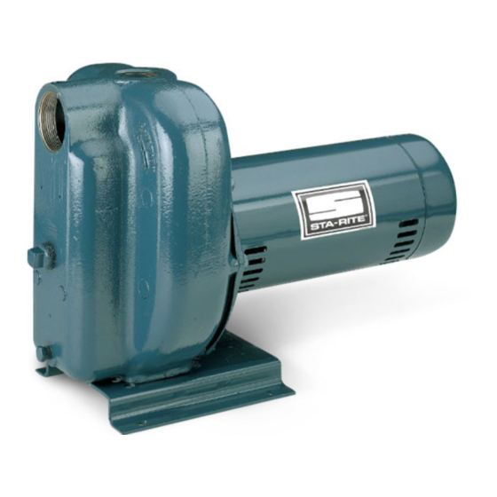
Self-Priming Centrifugal Pump
MODELS
1-1/2 HP
DS2HF-192PL
DS2HG-102L
DS2HF3-192P
DS2HG3-102
DS2 Series 60 Cycle
2 HP
2-1/2 HP
DS2HHG-53L
DS2HHG3-53
OWNER'S MANUAL
S30 (10/31/12)
Advertisement
Table of Contents

Related Manuals for Pentair STA-RITE DS2HE-191PL


Summary of Contents for Pentair STA-RITE DS2HE-191PL
- Page 1 DS2 Series 60 Cycle Self-Priming Centrifugal Pump MODELS 1 HP 1-1/2 HP 2 HP 2-1/2 HP DS2HE-191PL DS2HF-192PL DS2HG-102L DS2HHG-53L DS2HE3-191P DS2HF3-192P DS2HG3-102 DS2HHG3-53 293 WRIGHT STREET, DELAVAN, WI 53115 WWW.STA-RITE.COM PH: 888-782-7483 S30 (10/31/12) © 2012 Pentair, Inc. All Rights Reserved.
- Page 2 READ AND FOLLOW General Safety SAFETY INSTRUCTIONS! WarNING This is the safety alert symbol. When you see Hazardous pressure! this symbol on your pump or in this manual, look for Do not run pump one of the following signal words and be alert to the against closed discharge.
-
Page 3: Driven Point Installation
Well Pipe Installation NOTICE: Use the installation method below which Priming plug matches your well type. CaSED WEll INSTallaTION Priming tee 1. Inspect foot valve to be sure it works freely. Inspect Suction pipe strainer to be sure it is clean. 2. -
Page 4: Pump/Piping Installation
laWN SPrINKlING aPPlICaTION 2. Support all piping connected to the pump. This pump is designed for lawn sprinkling. It is 1 0 0 de signed to deliver plenty of water at full sprinkler pres- sure. It can pump from a pond, cistern or well points. Pump discharge can be divided to supply two (2) or more sprinkler systems. -
Page 5: Electrical Installation
NOTICE: Install pump as close to well head as poss- 7. Connect current carrying conductors to terminals L 1 ible. Long piping runs and many fittings create friction and L 2 under motor canopy. When replacing motor, and reduce flow. check wiring diagram on motor nameplate against Figure 8, below. -
Page 6: Operation
NOTICE: NEVEr run pump dry. Running pump with- out water in it will damage seals and can melt impeller and diffuser. To prevent damage, fill pump with water before starting. 1. Remove priming plug (Figure 10). Figure 8 – Changing the Voltage Setting 3025 0997 Figure 10 –... -
Page 7: Maintenance
Maintenance 5. Start pump: water should be produced in 10 mins. or less, the time depending on depth to water (not Pump and piping need not be disconnected to repair more than 20’) and length of horizontal run (10’ of or replace motor or seal (see Figure 14). - Page 8 3028 0997 3029 0997 Figure 15 – remove Diffuser Figure 17 – remove Seal plate 2. If impeller must be replaced, loosen two machine 4. Remove nuts from studs holding seal plate to motor. screws and remove motor canopy (see Figure 16). Carefully slide seal plate off of shaft.
-
Page 9: Pump Reassembly
To avoid electrical shock hazard, use insulated-handle screwdriver to short capacitor terminals as shown. 3031 0997 739 0993 Figure 19 – Press in New Seal Figure 21 – Hold Shaft 5. Dispose of cardboard washer and recheck seal PUMP rEaSSEMBlY face to be sure it is free of dirt, foreign particles, scratches and grease. -
Page 10: Troubleshooting Chart
Troubleshooting Chart SYMPTOM POSSIBlE CaUSE(S) COrrECTIVE aCTION Motor will not run Disconnect switch is off Be sure switch is on Fuse is blown Replace fuse Starting switch is defective Replace starting switch Wires at motor are loose, Refer to instructions on wiring. Check and tighten all wiring. disconnected, or wired incorrectly Capacitor voltage may be hazardous. - Page 11 2419A 0605 MODEl NUMBEr DS2HE191Pl DS2HF192Pl DS2HG102l DS2HHG53l Part DS2HE3191P DS2HF3192P DS2HG3102 DS2HHG353 Description 1 HP 11/2 HP 2 HP 21/2 HP Motor, 115/230V, 1 Phase A100ELL A100FLL — — Motor, 230V, 1 Phase — — A100GSLL AE100G5LL Motor, 230/460V, 3 Phase AP100EL AP100FL AP100GL...
-
Page 12: Limited Warranty
Limited Warranty STA-RITE warrants to the original consumer purchaser (“Purchaser” or “You”) of the products listed below, that they will be free from defects in material and workmanship for the Warranty Period shown below. Product Warranty Period whichever occurs first: Water Systems Products —...
Need help?
Do you have a question about the STA-RITE DS2HE-191PL and is the answer not in the manual?
Questions and answers