IEI Technology IMB-H810-i2 User Manual
Microatx motherboard iwth lga1150 intel core i7/i5/i3
Hide thumbs
Also See for IMB-H810-i2:
- User manual (172 pages) ,
- Quick installation manual (16 pages) ,
- User manual (172 pages)
Table of Contents
Advertisement
Quick Links
IMB-H810-i2 microATX Motherboard
MODEL:
IMB-H810-i2
microATX Motherboard with LGA1150 Intel® Core™ i7/i5/i3,
Pentium® or Celeron® CPU, Intel® H81 Chipset, Dual GbE,
DDR3, Internal DisplayPort, VGA, USB 3.0, COM Ports
Four SATA 6Gb/s Ports, IPMI 2.0 and RoHS
User Manual
Page i
Rev. 1.01 –13 March, 2014
Advertisement
Table of Contents

Related Manuals for IEI Technology IMB-H810-i2


Summary of Contents for IEI Technology IMB-H810-i2
-
Page 1: User Manual
IMB-H810-i2 microATX Motherboard MODEL: IMB-H810-i2 microATX Motherboard with LGA1150 Intel® Core™ i7/i5/i3, Pentium® or Celeron® CPU, Intel® H81 Chipset, Dual GbE, DDR3, Internal DisplayPort, VGA, USB 3.0, COM Ports Four SATA 6Gb/s Ports, IPMI 2.0 and RoHS User Manual Page i... - Page 2 IMB-H810-i2 microATX Motherboard Revision Date Version Changes 13 March, 2014 1.01 Deleted I C information 13 January, 2014 1.00 Initial release Page ii...
- Page 3 IMB-H810-i2 microATX Motherboard Copyright COPYRIGHT NOTICE The information in this document is subject to change without prior notice in order to improve reliability, design and function and does not represent a commitment on the part of the manufacturer. In no event will the manufacturer be liable for direct, indirect, special, incidental, or consequential damages arising out of the use or inability to use the product or documentation, even if advised of the possibility of such damages.
-
Page 4: Table Of Contents
PTIONAL TEMS 3 CONNECTORS ......................15 3.1 P ..............16 ERIPHERAL NTERFACE ONNECTORS 3.1.1 IMB-H810-i2 Layout..................16 3.1.2 Peripheral Interface Connectors ..............17 3.1.3 External Interface Panel Connectors............... 18 3.2 I ..............18 NTERNAL ERIPHERAL ONNECTORS 3.2.1 ATX Power Connector ..................18 3.2.2 Battery Connector.................... - Page 5 IMB-H810-i2 microATX Motherboard 3.2.11 Memory Card Slots..................28 3.2.12 Parallel Port Connector ................29 3.2.13 PCI Express Power Connector ..............31 3.2.14 Power Button ....................31 3.2.15 SATA 6Gb/s Drive Connectors............... 32 3.2.16 Serial Port Connectors (COM3~COM6), RS-232 ......... 33 3.2.17 Serial Port Connectors (COM7~COM10), RS-232 ........
- Page 6 IMB-H810-i2 microATX Motherboard 4.4 I ............64 NTERNAL ERIPHERAL EVICE ONNECTIONS 4.4.1 SATA Drive Connection ................... 64 4.5 E ........... 65 XTERNAL ERIPHERAL NTERFACE ONNECTION 4.5.1 Audio Connector ....................65 4.5.2 LAN Connection....................66 4.5.3 PS/2 Keyboard and Mouse Connection ............67 4.5.4 Serial Device Connection ................
- Page 7 IMB-H810-i2 microATX Motherboard 5.3.10 Serial Port Console Redirection ..............103 5.3.11 iEi Feature....................106 5.4 C ......................... 107 HIPSET 5.4.1 PCH-IO Configuration .................. 108 5.4.1.1 PCI Express Configuration ..............110 5.4.1.2 PCH Azalia Configuration ...............111 5.4.2 System Agent (SA) Configuration ..............112 5.4.2.1 Graphics Configuration................113...
- Page 8 IMB-H810-i2 microATX Motherboard C.2.4 Building the Recovery Partition..............160 C.2.5 Create Factory Default Image ..............162 C.3 A ..............167 ECOVERY ETUP ROCEDURE C.4 S ................172 ETUP ROCEDURE FOR INUX C.5 R ................175 ECOVERY UNCTIONS C.5.1 Factory Restore ..................... 177 C.5.2 Backup System....................
- Page 9 IMB-H810-i2 microATX Motherboard List of Figures Figure 1-1: IMB-H810-i2........................2 Figure 1-2: Connectors ........................4 Figure 1-3: IMB-H810-i2 Dimensions (mm) ..................5 Figure 1-4: Data Flow Diagram......................6 Figure 3-1: Connectors and Jumpers..................16 Figure 3-2: ATX Power Connector Location ................19 Figure 3-3: Battery Connector Location..................20 Figure 3-4: Chassis Intrusion Connector Location..............21...
- Page 10 IMB-H810-i2 microATX Motherboard Figure 3-27: PS/2 Pinouts ......................44 Figure 3-28: Ethernet Connector....................45 Figure 3-29: Serial Port Connector Pinouts................48 Figure 3-30: VGA Connector .......................49 Figure 4-1: Disengage the CPU Socket Load Lever..............53 Figure 4-2: Remove Protective Cover..................54 Figure 4-3: Insert the Socket LGA1150 CPU................55 Figure 4-4: Close the Socket LGA1150 ..................56...
- Page 11 IMB-H810-i2 microATX Motherboard Figure 6-10: Graphics Driver Read Me File ................130 Figure 6-11: Graphics Driver Setup Operations ..............130 Figure 6-12: Graphics Driver Installation Finish Screen ............131 Figure 6-13: Windows Control Panel ..................132 Figure 6-14: System Control Panel ..................132 Figure 6-15: Device Manager List ....................
- Page 12 IMB-H810-i2 microATX Motherboard Figure C-19: Image Creation Complete ................... 166 Figure C-20: Image Creation Complete ................... 166 Figure C-21: Press Any Key to Continue ................167 Figure C-22: Auto Recovery Utility ..................168 Figure C-23: Disable Automatically Restart................169 Figure C-24: Launching the Recovery Tool ................169 Figure C-25: Auto Recovery Environment for Windows ............
- Page 13 IMB-H810-i2 microATX Motherboard List of Tables Table 1-1: IMB-H810-i2 Specifications..................8 Table 2-1: Packing List.........................12 Table 2-2: Optional Items......................14 Table 3-1: Peripheral Interface Connectors ................18 Table 3-2: Rear Panel Connectors ....................18 Table 3-3: ATX Power Connector Pinouts .................19 Table 3-4: Battery Connector Pinouts ..................20 Table 3-5: Chassis Intrusion Connector Pinouts ..............21...
- Page 14 IMB-H810-i2 microATX Motherboard Table 3-28: Connector LEDs......................46 Table 3-29: USB 3.0 Port Pinouts....................46 Table 3-30: LAN1 Pinouts ......................47 Table 3-31: COM1 Serial Port Connector Pinouts ..............47 Table 3-32: COM2 Serial Port Connector Pinouts ..............47 Table 3-33: VGA Connector Pinouts...................48 Table 4-1: COM 10 Function Select Jumper Settings ...............61 Table 4-2: Flash Descriptor Security Override Jumper Settings..........62...
- Page 15 IMB-H810-i2 microATX Motherboard BIOS Menus BIOS Menu 1: Main ........................78 BIOS Menu 2: Advanced ......................79 BIOS Menu 3: ACPI Configuration ....................80 BIOS Menu 4: RTC Wake Settings ....................81 BIOS Menu 5: Trusted Computing ....................82 BIOS Menu 6: CPU Information....................83 BIOS Menu 7: SATA Configuration .....................86 BIOS Menu 8: USB Configuration ....................87...
-
Page 17: Introduction
IMB-H810-i2 microATX Motherboard Chapter Introduction Page 1... -
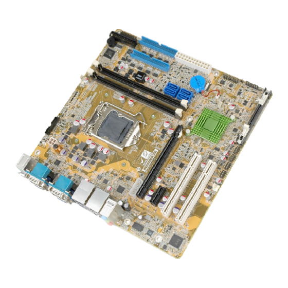
Page 18: Introduction
1.1 Introduction Figure 1-1: IMB-H810-i2 The IMB-H810-i2 is a microATX motherboard. It accepts a Socket LGA1150 Intel® Core™ i7, Core™ i5, Core™ i3, Pentium® or Celeron® processor and supports two 240-pin 1333/1066 MHz dual-channel DDR3 DIMM modules up to 16.0 GB maximum. -
Page 19: Benefits
Staying connected with both wired LAN connections Speedy running of multiple programs and applications 1.3 Features Some of the IMB-H810-i2 motherboard features are listed below: microATX form factor RoHS compliant LGA1150 Intel® Core™ i7, Core™ i5, Core™ i3, Pentium® or Celeron®... -
Page 20: Connectors
IMB-H810-i2 microATX Motherboard 1.4 Connectors The connectors on the IMB-H810-i2 are shown in the figure below. Figure 1-2: Connectors Page 4... -
Page 21: Dimensions
IMB-H810-i2 microATX Motherboard 1.5 Dimensions The main dimensions of the IMB-H810-i2 are shown in the diagram below. Figure 1-3: IMB-H810-i2 Dimensions (mm) Page 5... -
Page 22: Data Flow
IMB-H810-i2 microATX Motherboard 1.6 Data Flow F igure 1-4 shows the data flow between the system chipset, the CPU and other components installed on the motherboard. Figure 1-4: Data Flow Diagram Page 6... -
Page 23: Technical Specifications
IMB-H810-i2 microATX Motherboard 1.7 Technical Specifications IMB-H810-i2 technical specifications are listed below. Specification/Model IMB-H810-i2 microATX Form Factor LGA1150 Intel® Core™ i7, Core™ i5, Core™ i3, Pentium® or Celeron® CPU Supported processor supported Chipset Intel® H81 Integrated Graphics Intel® HD Graphics Gen 7.5 supports DirectX 11.1, OpenCL 1.2, OpenGL 3.2, Full MPEG2, VC1, AVC Decode... -
Page 24: Table 1-1: Imb-H810-I2 Specifications
(3.90GHz Intel® i7-4770K CPU with two 4GB 1333MHz DDR3 DIMMs) Operating Temperature -10ºC ~ 60ºC Storage Temperature -20ºC ~ 70ºC 5% ~ 95% (non-condensing) Humidity Physical Specifications 244 mm x 244 mm Dimensions 1200 g / 680 g Weight GW/NW Table 1-1: IMB-H810-i2 Specifications Page 8... -
Page 25: Packing List
IMB-H810-i2 microATX Motherboard Chapter Packing List Page 9... -
Page 26: Anti-Static Precautions
Only handle the edges of the PCB: Don't touch the surface of the motherboard. Hold the motherboard by the edges when handling. 2.2 Unpacking Precautions When the IMB-H810-i2 is unpacked, please do the following: Follow the antistatic guidelines above. Make sure the packing box is facing upwards when opening. -
Page 27: Packing List
Contact the IEI reseller or vendor the IMB-H810-i2 was purchased from or contact sales representative directly by sending an email to ales@ieiworld.com.tw. The IMB-H810-i2 is shipped with the following components: Quantity Item and Part Number Image IMB-H810-i2 single board computer SATA cable (P/N: 32000-062800-RS) I/O shielding (P/N: 45014-0041C0-00-RS) Mini jumper pack (2.54mm) -
Page 28: Optional Items
IMB-H810-i2 microATX Motherboard Quantity Item and Part Number Image Quick Installation Guide Table 2-1: Packing List 2.4 Optional Items The following are optional components which may be separately purchased: Item and Part Number Image IPMI 2.0 adapter card with AST2400 BMC chip... - Page 29 IMB-H810-i2 microATX Motherboard Item and Part Number Image Parallel port cable (P/N:19800-000049-RS) LGA1155/LGA1156 cooler kit (1U chassis compatible, 73W) (P/N: CF-1156A-RS-R11) LGA1155/LGA1156 cooler kit (95W) (P/N: CF-1156E-R11) DisplayPort to HDMI converter board for IEI IDP connector (P/N: DP-HDMI-R10) DisplayPort to 24-bit dual-channel LVDS converter board...
-
Page 30: Table 2-2: Optional Items
IMB-H810-i2 microATX Motherboard Item and Part Number Image 20-pin Infineon TPM Module, S/W management tool, firmware V3.17 (P/N: TPM-IN01-R11) Table 2-2: Optional Items Page 14... -
Page 31: Connectors
IMB-H810-i2 microATX Motherboard Chapter Connectors Page 15... -
Page 32: Peripheral Interface Connectors
IMB-H810-i2 microATX Motherboard 3.1 Peripheral Interface Connectors This chapter details all the jumpers and connectors. 3.1.1 IMB-H810-i2 Layout The figures below show all the connectors and jumpers. Figure 3-1: Connectors and Jumpers Page 16... -
Page 33: Peripheral Interface Connectors
IMB-H810-i2 microATX Motherboard 3.1.2 Peripheral Interface Connectors The table below lists all the connectors on the board. Connector Type Label ATX Power connector 24-pin connector ATX1 Battery connector 2-pin wafer BAT1 Chassis intrusion connector 2-pin header CHASSIE1 CPU power connector... -
Page 34: External Interface Panel Connectors
COM1, COM2 VGA connectors 15-pin female VGA1, VGA2 Table 3-2: Rear Panel Connectors 3.2 Internal Peripheral Connectors The section describes all of the connectors on the IMB-H810-i2. 3.2.1 ATX Power Connector CN Label: ATX1 CN Type: 24-pin ATX CN Location:... -
Page 35: Figure 3-2: Atx Power Connector Location
IMB-H810-i2 microATX Motherboard The ATX power connector connects to an ATX power supply. Figure 3-2: ATX Power Connector Location Description Description +3.3V +3.3V +3.3V -12V PS_ON Power good 5VSB +12V +12V +3.3V Table 3-3: ATX Power Connector Pinouts Page 19... -
Page 36: Battery Connector
IMB-H810-i2 microATX Motherboard 3.2.2 Battery Connector CAUTION: Risk of explosion if battery is replaced by an incorrect type. Only certified engineers should replace the on-board battery. Dispose of used batteries according to instructions and local regulations. CN Label: BAT1 CN Type:... -
Page 37: Chassis Intrusion Connector
IMB-H810-i2 microATX Motherboard 3.2.3 Chassis Intrusion Connector CN Label: CHASSIE1 2-pin header CN Type: CN Location: F igure 3-4 CN Pinouts: T able 3-5 The chassis intrusion connector is for a chassis intrusion detection sensor or switch that detects if a chassis component is removed or replaced. -
Page 38: Displayport Connector
IMB-H810-i2 microATX Motherboard CN Location: See Figure 3-5 CN Pinouts: See Table 3-6 The CPU power input connector provides power to the CPU. Figure 3-5: CPU Power Connector Location PIN NO. DESCRIPTION +12V +12V Table 3-6: CPU Power Connector Pinouts 3.2.5 DisplayPort Connector... -
Page 39: Fan Connector (Cpu)
IMB-H810-i2 microATX Motherboard Figure 3-6: DisplayPort Connector Location PIN NO. DESCRIPTION PIN NO. DESCRIPTION AUXP LANE1N AUXN LANE1P LANE2P LANE3N LANE2N LANE3P LANE0P AUX_CTRL_DET_D LANE0N +3.3V Table 3-7: DisplayPort Connector Pinouts 3.2.6 Fan Connector (CPU) CN Label: CPU_FAN1 CN Type:... -
Page 40: Fan Connectors (System)
IMB-H810-i2 microATX Motherboard Figure 3-7: CPU Fan Connector Location PIN NO. DESCRIPTION +12 V FANIO Table 3-8: CPU Fan Connector Pinouts 3.2.7 Fan Connectors (System) CN Label: SYS_FAN1 CN Type: 3-pin wafer CN Location: See Figure 3-8 CN Pinouts: See Table 3-9 Each fan connector attaches to a system cooling fan. -
Page 41: Front Panel Connector
IMB-H810-i2 microATX Motherboard Figure 3-8: System Fan Connector Locations PIN NO. DESCRIPTION FANIO +12 V (PWM) Table 3-9: System Fan Connector Pinouts 3.2.8 Front Panel Connector CN Label: F_PANEL1 CN Type: 14-pin header CN Location: See Figure 3-9 See Table 3-10... -
Page 42: Iris Module Slot
IMB-H810-i2 microATX Motherboard Figure 3-9: Front Panel Connector Location FUNCTION DESCRIPTION FUNCTION DESCRIPTION Power LED PWR_LED+ Speaker Speaker+ IPMI LED IPMI ID_LED+ PWR_LED- IPMI ID_LED- Power Button PWR_BTN+ Speaker Speaker- PWR_BTN- HDD LED HDD_LED+ Reset RESET+ HDD_LED- RESET- Table 3-10: Front Panel Connector Pinouts 3.2.9 iRIS Module Slot... -
Page 43: Lan Led Connectors
The iRIS module slot is designed to install the IEI iRIS-2400 IPMI 2.0 module only. DO NOT install other modules into the iRIS module slot. Doing so may cause damage to the IMB-H810-i2. Figure 3-10: iRIS Module Slot Location 3.2.10 LAN LED Connectors... -
Page 44: Memory Card Slots
IMB-H810-i2 microATX Motherboard Figure 3-11: LAN LED Connector Locations Description Active+ Active- Table 3-11: LAN1 LED Connector (LED_LAN1) Pinouts Description Active+ Active- Table 3-12: LAN2 LED Connector (LED_LAN2) Pinouts 3.2.11 Memory Card Slots CN Label: CHA_DIMM1, CHB_DIMM1 DDR3 DIMM slot... -
Page 45: Parallel Port Connector
IMB-H810-i2 microATX Motherboard Figure 3-12: Memory Card Slot Locations 3.2.12 Parallel Port Connector CN Label: LPT1 CN Type: 26-pin box header CN Location: See Figure 3-13 CN Pinouts: See Table 3-13 The parallel port connector connects to a parallel port connector interface or some other parallel port device such as a printer. -
Page 46: Figure 3-13: Parallel Port Connector Location
IMB-H810-i2 microATX Motherboard Figure 3-13: Parallel Port Connector Location Description Description STROBE# DATA 0 DATA 1 DATA 2 DATA 3 DATA 4 DATA 5 DATA 6 DATA 7 ACKNOWLEDGE# BUSY PAPER EMPTY PRINTER SELECT AUTO FORM FEED # ERROR# INITIALIZE#... -
Page 47: Pci Express Power Connector
IMB-H810-i2 microATX Motherboard 3.2.13 PCI Express Power Connector CN Label: ATXPWR1 4-pin connector CN Type: CN Location: See Figure 3-14 CN Pinouts: See Table 3-14 The PCIe power connector provides extra power to the PCIe expansion card. Figure 3-14: PCIe Power Location... -
Page 48: Sata 6Gb/S Drive Connectors
IMB-H810-i2 microATX Motherboard The on-board power button controls system power. Figure 3-15: Power Button Location 3.2.15 SATA 6Gb/s Drive Connectors CN Label: S_ATA1, S_ATA2, S_ATA3, S_ATA4 CN Type: 7-pin SATA drive connectors CN Location: See Figure 3-16 CN Pinouts: See Table 3-15 The SATA drive connectors can be connected to SATA drives. -
Page 49: Serial Port Connectors (Com3~Com6), Rs-232
IMB-H810-i2 microATX Motherboard Figure 3-16: SATA 6Gb/s Drive Connector Locations Description SATA_TX+ SATA_TX- SATA_RX- SATA_RX+ Table 3-15: SATA 6Gb/s Drive Connector Pinouts 3.2.16 Serial Port Connectors (COM3~COM6), RS-232 CN Label: COM3-6 CN Type: 40-pin box header CN Location: See Figure 3-17... -
Page 50: Figure 3-17: Serial Port Connector (Com3~Com6) Location
IMB-H810-i2 microATX Motherboard Figure 3-17: Serial Port Connector (COM3~COM6) Location PIN NO. DESCRIPTION PIN NO. DESCRIPTION COM3 COM4 COM5 COM6 Page 34... -
Page 51: Serial Port Connectors (Com7~Com10), Rs-232
IMB-H810-i2 microATX Motherboard PIN NO. DESCRIPTION PIN NO. DESCRIPTION Table 3-16: COM3~6 Serial Port Connector Pinouts 3.2.17 Serial Port Connectors (COM7~COM10), RS-232 CN Label: COM7-10 CN Type: 40-pin box header CN Location: See Figure 3-18 CN Pinouts: See Table 3-17 The connector provides four RS-232 ports connection. -
Page 52: Serial Port Connector (Com10), Rs-422/485
IMB-H810-i2 microATX Motherboard PIN NO. DESCRIPTION PIN NO. DESCRIPTION COM8 COM9 COM10 Table 3-17: COM7~10 Serial Port Connector Pinouts 3.2.18 Serial Port Connector (COM10), RS-422/485 CN Label: CN10 CN Type: 4-pin wafer CN Location: See Figure 3-19 CN Pinouts: See Table 3-18 Used for RS-422/485 communications. -
Page 53: Figure 3-19: Rs-422/485 Connector Location
IMB-H810-i2 microATX Motherboard Figure 3-19: RS-422/485 Connector Location PIN NO. DESCRIPTION RXD422- RXD422+ TXD422+/TXD485+ TXD422-/TXD485- Table 3-18: RS-422/485 Connector Pinouts Use the optional RS-422/485 cable to connect to a serial device. The pinouts of the DB-9 connector are listed below. -
Page 54: Smbus Connector
IMB-H810-i2 microATX Motherboard 3.2.19 SMBus Connector CN Label: 4-pin wafer CN Type: CN Location: See Figure 3-20 CN Pinouts: See Table 3-20 The SMBus (System Management Bus) connector provides low-speed system management communications. Figure 3-20: SMBus Connector Location DESCRIPTION SMB_DATA... -
Page 55: Spi Flash Connector
IMB-H810-i2 microATX Motherboard 3.2.20 SPI Flash Connector CN Label: JSPI1 8-pin header CN Type: CN Location: See Figure 3-21 CN Pinouts: See Table 3-21 The SPI flash connector is used to flash the SPI ROM. Figure 3-21: SPI Flash Connector Location PIN NO. -
Page 56: Tpm Connector
IMB-H810-i2 microATX Motherboard CN Location: See Figure 3-22 CN Pinouts: See Table 3-22 The SPI flash connector is used to flash the EC ROM. Figure 3-22: SPI EC Flash Connector Location PIN NO. DESCRIPTION PIN NO. DESCRIPTION +3.3V SPI_CS# SPI_SO... -
Page 57: Usb 2.0 Connectors
IMB-H810-i2 microATX Motherboard Figure 3-23: TPM Connector Location PIN NO. DESCRIPTION PIN NO. DESCRIPTION LCLK LFRAME# LRERST# LAD3 LAD2 +3.3V LAD1 LAD0 SB3V SERIRQ GLKRUN# LPCPD# LDRQ# Table 3-23: TPM Connector Pinouts 3.2.23 USB 2.0 Connectors CN Label: USB3, USB4, USB5, USB6... -
Page 58: External Peripheral Interface Connector Panel
IMB-H810-i2 microATX Motherboard The USB 2.0 connectors connect to USB 2.0 devices. Each pin header provides two USB 2.0 ports. Figure 3-24: USB 2.0 Connector Locations PIN NO. DESCRIPTION PIN NO. DESCRIPTION USB_DATA- USB_DATA+ USB_DATA+ USB_DATA- Table 3-24: USB 2.0 Connector Pinouts 3.3 External Peripheral Interface Connector Panel... -
Page 59: Audio Connector
IMB-H810-i2 microATX Motherboard Figure 3-25: External Peripheral Interface Connector 3.3.1 Audio Connector CN Label: AUDIO_CV1 CN Type: Audio jack CN Location: See Figure 3-25 The audio jacks connect to external audio devices. Line In port (Light Blue): Connects a CD-ROM, DVD player, or other audio devices. -
Page 60: Keyboard And Mouse Connectors
IMB-H810-i2 microATX Motherboard 3.3.2 Keyboard and Mouse Connectors CN Label: KBMS1 PS/2 CN Type: CN Location: See Figure 3-25 CN Pinouts: See Figure 3-27 and Table 3-25 The PS/2 ports are for connecting a PS/2 mouse and a PS/2 keyboard. -
Page 61: Ethernet And Usb 2.0 Connectors
IMB-H810-i2 microATX Motherboard 3.3.3 Ethernet and USB 2.0 Connectors CN Label: LAN2_USB2 RJ-45, USB 3.0 CN Type: CN Location: See Figure 3-25 CN Pinouts: See Table 3-26 and Table 3-27 The USB 2.0 connector can be connected to a USB device. -
Page 62: Ethernet And Usb 3.0 Connectors
CN Label: LAN1_USB1 CN Type: RJ-45, USB 3.0 CN Location: See Figure 3-25 CN Pinouts: See Table 3-29 and Table 3-30 There are two external USB 3.0 connectors on the IMB-H810-i2. DESCRIPTION DESCRIPTION USB_DATA- USB_DATA- USB_DATA+ USB_ DATA+ USB3_RX- USB3_RX-... -
Page 63: Serial Port Connectors (Com1, Com2)
IMB-H810-i2 microATX Motherboard DESCRIPTION DESCRIPTION LAN1_MDI1P LAN1_MDI3P LAN1_MDI1N LAN1_MDI3N Table 3-30: LAN1 Pinouts 3.3.5 Serial Port Connectors (COM1, COM2) CN Label: COM1, COM2 DB-9 connector CN Type: CN Location: See Figure 3-25 CN Pinouts: See Table 3-31, Table 3-32 The serial port connects to a RS-232 serial communications device. -
Page 64: Vga Connectors
IMB-H810-i2 microATX Motherboard Figure 3-29: Serial Port Connector Pinouts 3.3.6 VGA Connectors CN Label: VGA1, VGA2 CN Type: 15-pin Female See Figure 3-25 CN Location: CN Pinouts: See Table 3-33 and Figure 3-30 Both VGA connectors can be connected to monitors that accept standard VGA input for easy dual display setup. -
Page 65: Figure 3-30: Vga Connector
IMB-H810-i2 microATX Motherboard Figure 3-30: VGA Connector Page 49... -
Page 66: Installation
IMB-H810-i2 microATX Motherboard Chapter Installation Page 50... -
Page 67: Anti-Static Precautions
Electrostatic discharge (ESD) can cause serious damage to electronic components, including the IMB-H810-i2. Dry climates are especially susceptible to ESD. It is therefore critical that whenever the IMB-H810-i2 or any other electrical component is handled, the following anti-static precautions are strictly adhered to. - Page 68 This helps to prevent potential ESD damage. Turn all power to the IMB-H810-i2 off: When working with the IMB-H810-i2, make sure that it is disconnected from all power supplies and that no electricity is being fed into the system.
-
Page 69: Socket Lga1150 Cpu Installation
IMB-H810-i2 microATX Motherboard 4.2.1 Socket LGA1150 CPU Installation WARNING: CPUs are expensive and sensitive components. When installing the CPU please be careful not to damage it in anyway. Make sure the CPU is installed properly and ensure the correct cooling kit is properly installed. -
Page 70: Figure 4-2: Remove Protective Cover
IMB-H810-i2 microATX Motherboard Figure 4-2: Remove Protective Cover Step 3: Inspect the CPU socket. Make sure there are no bent pins and make sure the socket contacts are free of foreign material. If any debris is found, remove it with compressed air. -
Page 71: Figure 4-3: Insert The Socket Lga1150 Cpu
IMB-H810-i2 microATX Motherboard Step 6: Align the CPU pins. Locate pin 1 and the two orientation notches on the CPU. Carefully match the two orientation notches on the CPU with the socket alignment keys. Step 7: Insert the CPU. Gently insert the CPU into the socket. If the CPU pins are properly aligned, the CPU should slide into the CPU socket smoothly. -
Page 72: Socket Lga1150 Cooling Kit Installation
IMB-H810-i2 microATX Motherboard Figure 4-4: Close the Socket LGA1150 Step 9: Connect the 12 V power to the board. Connect the 12 V power from the power supply to the board. Step 0: 4.2.2 Socket LGA1150 Cooling Kit Installation WARNING: DO NOT attempt to install a push-pin cooling fan. -
Page 73: Figure 4-6: Cooling Kit Support Bracket
IMB-H810-i2 microATX Motherboard WARNING: Do not wipe off (accidentally or otherwise) the pre-sprayed layer of thermal paste on the bottom of the heat sink. The thermal paste between the CPU and the heat sink is important for optimum heat dissipation. -
Page 74: Dimm Installation
IMB-H810-i2 microATX Motherboard Step 5: Connect the fan cable. Connect the cooling kit fan cable to the fan connector on the IMB-H810-i2. Carefully route the cable and avoid heat generating chips and fan blades. 4.2.3 DIMM Installation To install a DIMM, please follow the steps below and refer to Figure 4-7. -
Page 75: Iris-2400 Module Installation
The iRIS module slot is designed to install the IEI iRIS-2400 IPMI 2.0 module only. DO NOT install other modules into the iRIS module slot. Doing so may cause damage to the IMB-H810-i2. To install the iRIS-2400 module, please follow the steps below and refer to Figure 4-8. -
Page 76: System Configuration
IMB-H810-i2 microATX Motherboard Step 5: Removing the iRIS-2400 module. To remove the iRIS-2400 module, push both handles outward. The module is ejected by a mechanism in the socket.Step 0: NOTE: After installing the iRIS-2400 module, use LAN2 port to establish a network connection. -
Page 77: Clear Cmos Button
IMB-H810-i2 microATX Motherboard 4.3.2 Clear CMOS Button To reset the BIOS, remove the on-board battery and press the clear CMOS button for three seconds or more. The clear CMOS button location is shown in Figure 4-10. Figure 4-10: Clear CMOS Button Location 4.3.3 COM 10 Function Select... -
Page 78: Flash Descriptor Security Override
IMB-H810-i2 microATX Motherboard Figure 4-11: COM 10 Function Select Jumper Location 4.3.4 Flash Descriptor Security Override The Flash Descriptor Security Override jumper specifies whether to override the flash descriptor. Setting Description Short 1-2 No override (Default) Short 2-3 Override Table 4-2: Flash Descriptor Security Override Jumper Settings... -
Page 79: Pcie X16 Interface Setup
IMB-H810-i2 microATX Motherboard Figure 4-12: Flash Descriptor Security Override Jumper Location 4.3.5 PCIe x16 Interface Setup The PCIe x16 interface setup is made through the BIOS options in “Chipset PCH-IO Configuration” BIOS menu. Use the PCIEX16 Power option to configure the PCIe x16 channel mode. -
Page 80: Internal Peripheral Device Connections
This section outlines the installation of peripheral devices to the onboard connectors. 4.4.1 SATA Drive Connection The IMB-H810-i2 is shipped with two SATA drive cables. To connect the SATA drives to the connectors, please follow the steps below. Step 1: Locate the connectors. -
Page 81: External Peripheral Interface Connection
This section describes connecting devices to the external connectors on the IMB-H810-i2. 4.5.1 Audio Connector The audio jacks on the external audio connector enable the IMB-H810-i2 to be connected to a stereo sound setup. Each jack supports both input and output. When connecting a device, the High Definition Audio utility will automatically detect input or output. -
Page 82: Lan Connection
Locate the RJ-45 connectors. The locations of the USB connectors are shown in Chapter 3. Step 2: Align the connectors. Align the RJ-45 connector on the LAN cable with one of the RJ-45 connectors on the IMB-H810-i2. See Figure 4-16. Page 66... -
Page 83: Ps/2 Keyboard And Mouse Connection
RJ-45 connector into the on-board RJ-45 connector. 4.5.3 PS/2 Keyboard and Mouse Connection The IMB-H810-i2 has a dual PS/2 connector on the external peripheral interface panel. The dual PS/2 connector is used to connect to a keyboard and mouse to the system. -
Page 84: Serial Device Connection
IMB-H810-i2 microATX Motherboard Figure 4-17: PS/2 Keyboard/Mouse Connector 4.5.4 Serial Device Connection The IMB-H810-i2 has two single male DB-9 connectors on the external peripheral interface panel for a serial device. Follow the steps below to connect a serial device to the IMB-H810-i2. -
Page 85: Usb Connection (Dual Connector)
IMB-H810-i2 microATX Motherboard Figure 4-18: Serial Device Connector Step 3: Secure the connector. Secure the serial device connector to the external interface by tightening the two retention screws on either side of the connector. Step 0: 4.5.5 USB Connection (Dual Connector) The external USB Series "A"... -
Page 86: Vga Monitor Connection
Figure 4-19: USB Connector 4.5.6 VGA Monitor Connection The IMB-H810-i2 has two single female DB-15 connectors on the external peripheral interface panel. The DB-15 connector is connected to a CRT or VGA monitor. To connect a monitor to the IMB-H810-i2, please follow the instructions below. -
Page 87: Ipmi Setup Procedure
The IMB-H810-i2 features Intelligent Platform Management Interface (IPMI) that helps lower the overall costs of server management by enabling users to maximize IT resources, save time and manage multiple systems. The IMB-H810-i2 supports IPMI 2.0 through the optional iRIS-2400 module. Follow the steps below to setup IPMI. -
Page 88: Using The Iei Iman Web Gui
IP address, follow the steps below: a. Copy the Ipmitool.exe file to a bootable USB flash drive. b. Insert the USB flash drive to the IMB-H810-i2 c. The IMB-H810-i2 boots from the USB flash drive d. Enter the following command: ipmitool 20 30 02 01 03 00 00 (there is a space between each two-digit number) e. -
Page 89: Figure 4-22: Iei Iman Web Gui
Figure 4-22: IEI iMAN Web GUI NOTE: To understand how to use the IEI iMAN Web GUI, please refer to the iRIS-2400 Web GUI user manual in the utility CD came with the IMB-H810-i2. The user manual describes each function in detail. Page 73... -
Page 90: Bios
IMB-H810-i2 microATX Motherboard Chapter BIOS Page 74... -
Page 91: Introduction
IMB-H810-i2 microATX Motherboard 5.1 Introduction The BIOS is programmed onto the BIOS chip. The BIOS setup program allows changes to certain system settings. This chapter outlines the options that can be changed. NOTE: Some of the BIOS options may vary throughout the life cycle of the product and are subject to change without prior notice. -
Page 92: Getting Help
IMB-H810-i2 microATX Motherboard Function Decrease the numeric value or make changes Esc key Main Menu – Quit and not save changes into CMOS Status Page Setup Menu and Option Page Setup Menu -- Exit current page and return to Main Menu... -
Page 93: Main
IMB-H810-i2 microATX Motherboard The following sections completely describe the configuration options found in the menu items at the top of the BIOS screen and listed above. 5.2 Main The Main BIOS menu (BIOS Menu 1) appears when the BIOS Setup program is entered. -
Page 94: Bios Menu 1: Main
IMB-H810-i2 microATX Motherboard Aptio Setup Utility – Copyright (C) 2012 American Megatrends, Inc. Main Advanced Chipset Boot Security Save & Exit BIOS Information Set the Date. Use Tab to BIOS Vendor American Megatrends switch between Data Core Version 4.6.5.4 elements. -
Page 95: Advanced
IMB-H810-i2 microATX Motherboard System Date [xx/xx/xx] Use the System Date option to set the system date. Manually enter the day, month and year. System Time [xx:xx:xx] Use the System Time option to set the system time. Manually enter the hours, minutes and seconds. -
Page 96: Acpi Settings
IMB-H810-i2 microATX Motherboard 5.3.1 ACPI Settings The ACPI Settings menu (BIOS Menu 3) configures the Advanced Configuration and Power Interface (ACPI) options. Aptio Setup Utility – Copyright (C) 2012 American Megatrends, Inc. Advanced ACPI Settings Select the highest ACPI sleep state the system... -
Page 97: Rtc Wake Settings
IMB-H810-i2 microATX Motherboard S3 (Suspend to The caches are flushed and the CPU is powered RAM) off. Power to the RAM is maintained. The computer returns slower to a working state, but more power is saved. 5.3.2 RTC Wake Settings The RTC Wake Settings menu (BIOS Menu 4) configures RTC wake event. -
Page 98: Trusted Computing
IMB-H810-i2 microATX Motherboard Enabled If selected, the following appears with values that can be selected: *Wake up every day *Wake up date *Wake up hour *Wake up minute *Wake up second After setting the alarm, the computer turns itself on from a suspend state when the alarm goes off. -
Page 99: Cpu Information
IMB-H810-i2 microATX Motherboard Security Device Support [Disable] Use the Security Device Support option to configure support for security devices. Security Device support is disabled. Disable EFAULT Enable Security Device support is enabled. 5.3.4 CPU Information Use the CPU Information submenu (BIOS Menu 6) to view detailed CPU specifications and configure the CPU. - Page 100 IMB-H810-i2 microATX Motherboard Processor Type: Lists the brand name of the CPU being used CPU Signature: Lists the CPU signature value. Microcode Patch: Lists the microcode patch being used. FSB Speed: Lists the front side bus (FSB) speed. Max CPU Speed: Lists the maximum CPU processing speed.
- Page 101 IMB-H810-i2 microATX Motherboard Enable one core in the processor package. Intel Virtualization Technology [Disabled] Use the Intel Virtualization Technology option to enable or disable virtualization on the system. When combined with third party software, Intel® Virtualization technology allows several OSs to run on the same system at the same time.
-
Page 102: Sata Configuration
IMB-H810-i2 microATX Motherboard 5.3.5 SATA Configuration Use the SATA Configuration menu (BIOS Menu 7) to change and/or set the configuration of the SATA devices installed in the system. Aptio Setup Utility – Copyright (C) 2012 American Megatrends, Inc. Advanced SATA Controller(s) -
Page 103: Usb Configuration
IMB-H810-i2 microATX Motherboard 5.3.6 USB Configuration Use the USB Configuration menu (BIOS Menu 8) to read USB configuration information and configure the USB settings. Aptio Setup Utility – Copyright (C) 2012 American Megatrends, Inc. Advanced USB Configuration Enables Legacy USB support. -
Page 104: F81866 Super Io Configuration
IMB-H810-i2 microATX Motherboard Disabled Legacy USB support disabled Legacy USB support disabled if no USB devices are Auto connected 5.3.7 F81866 Super IO Configuration Use the F81866 Super IO Configuration menu (BIOS Menu 9) to set or change the configurations for the parallel ports and serial ports. -
Page 105: Serial Port N Configuration
IMB-H810-i2 microATX Motherboard 5.3.7.1 Serial Port n Configuration Use the Serial Port n Configuration menu (BIOS Menu 10) to configure the serial port n. Aptio Setup Utility – Copyright (C) 2012 American Megatrends, Inc. Advanced Serial Port n Configuration Enable or Disable Serial... - Page 106 IMB-H810-i2 microATX Motherboard IO=3F8h; Serial Port I/O port address is 3F8h and the interrupt IRQ=3, 4 address is IRQ3,4 Serial Port I/O port address is 2C0h and the interrupt IO=2C0h; address is IRQ3, 4 IRQ=3, 4 IO=2C8h; Serial Port I/O port address is 2C8h and the interrupt...
- Page 107 IMB-H810-i2 microATX Motherboard 5.3.7.1.3 Serial Port 3 Configuration Serial Port [Enabled] Use the Serial Port option to enable or disable the serial port. Disabled Disable the serial port Enable the serial port Enabled EFAULT Change Settings [Auto] Use the Change Settings option to change the serial port IO port address and interrupt address.
- Page 108 IMB-H810-i2 microATX Motherboard Change Settings [Auto] Use the Change Settings option to change the serial port IO port address and interrupt address. Auto The serial port IO port address and interrupt address EFAULT are automatically detected. Serial Port I/O port address is 2E8h and the interrupt IO=2E8h;...
- Page 109 IMB-H810-i2 microATX Motherboard IO=2C0h; Serial Port I/O port address is 2C0h and the interrupt IRQ=10, 11 address is IRQ10, 11 Serial Port I/O port address is 2C8h and the interrupt IO=2C8h; address is IRQ10, 11 IRQ=10, 11 IO=2D0h; Serial Port I/O port address is 2D0h and the interrupt...
-
Page 110: Parallel Port Configuration
IMB-H810-i2 microATX Motherboard IO=2D0h; Serial Port I/O port address is 2D0h and the interrupt IRQ=10, 11 address is IRQ10, 11 Serial Port I/O port address is 2D8h and the interrupt IO=2D8h; address is IRQ10, 11 IRQ=10, 11 IO=2E0h; Serial Port I/O port address is 2E0h and the interrupt... -
Page 111: F81866 H/W Monitor
IMB-H810-i2 microATX Motherboard Auto The parallel port IO port address and interrupt EFAULT address are automatically detected. Parallel Port I/O port address is 378h and the IO=378h; interrupt address is IRQ5 IRQ=5 IO=378h; Parallel Port I/O port address is 378h and the... -
Page 112: Bios Menu 12: F81866 H/W Monitor
IMB-H810-i2 microATX Motherboard Aptio Setup Utility – Copyright (C) 2012 American Megatrends, Inc. Advanced PC Health Status Smart FAN Configuration > Smart Fan Mode Configuration CPU Temperature :+35 C SYS Temperature :+0 C CPU_FAN1 Speed :1821 RPM --------------------- SYS_FAN1 Speed... -
Page 113: Smart Fan Mode Configuration
IMB-H810-i2 microATX Motherboard 5.3.8.1 Smart Fan Mode Configuration Use the Smart Fan Mode Configuration submenu (BIOS Menu 13) to configure smart fan temperature and speed settings. Aptio Setup Utility – Copyright (C) 2012 American Megatrends, Inc. Advanced Smart Fan Mode Configuration... -
Page 114: F81216 Secondary Super Io Configuration
IMB-H810-i2 microATX Motherboard Fan start PWM Use the + or – key to change the Fan start PWM value. Enter a decimal number between 1 and 128. Fan slope PWM Use the + or – key to change the Fan slope PWM value. Enter a decimal number between 1 and 64. -
Page 115: Serial Port N Configuration
IMB-H810-i2 microATX Motherboard 5.3.9.1 Serial Port n Configuration Use the Serial Port n Configuration menu (BIOS Menu 10) to configure the serial port n. Aptio Setup Utility – Copyright (C) 2012 American Megatrends, Inc. Advanced Serial Port n Configuration Enable or Disable Serial... - Page 116 IMB-H810-i2 microATX Motherboard IO=260h; Serial Port I/O port address is 260h and the interrupt IRQ=10, 11 address is IRQ10, 11 Serial Port I/O port address is 268h and the interrupt IO=268h; address is IRQ10, 11 IRQ=10, 11 IO=270h; Serial Port I/O port address is 270h and the interrupt...
- Page 117 IMB-H810-i2 microATX Motherboard IO=278h; Serial Port I/O port address is 278h and the interrupt IRQ=10, 11 address is IRQ10, 11 5.3.9.1.3 Serial Port 9 Configuration Serial Port [Enabled] Use the Serial Port option to enable or disable the serial port.
- Page 118 IMB-H810-i2 microATX Motherboard 5.3.9.1.4 Serial Port 10 Configuration Serial Port [Enabled] Use the Serial Port option to enable or disable the serial port. Disabled Disable the serial port Enable the serial port Enabled EFAULT Change Settings [Auto] Use the Change Settings option to change the serial port IO port address and interrupt address.
-
Page 119: Serial Port Console Redirection
IMB-H810-i2 microATX Motherboard 5.3.10 Serial Port Console Redirection The Serial Port Console Redirection menu (BIOS Menu 16) allows the console redirection options to be configured. Console redirection allows users to maintain a system remotely by re-directing keyboard input and text output through the serial port. - Page 120 IMB-H810-i2 microATX Motherboard Console Redirection [Disabled] Use Console Redirection option to enable or disable the console redirection function. Disabled the console redirection function Disabled EFAULT Enabled Enabled the console redirection function The following options are available in the Console Redirection Settings submenu when the Console Redirection option is enabled.
- Page 121 IMB-H810-i2 microATX Motherboard Parity [None] Use the Parity option to specify the parity bit that can be sent with the data bits for detecting the transmission errors. None No parity bit is sent with the data bits. EFAULT The parity bit is 0 if the number of ones in the data Even bits is even.
-
Page 122: Iei Feature
IMB-H810-i2 microATX Motherboard 5.3.11 iEi Feature Use the iEi Feature menu (BIOS Menu 17) to configure IEI One Key Recovery function. Aptio Setup Utility – Copyright (C) 2012 American Megatrends, Inc. Advanced iEi Feature Auto Recovery Function Reboot and recover... -
Page 123: Chipset
IMB-H810-i2 microATX Motherboard 5.4 Chipset Use the Chipset menu (BIOS Menu 18) to access the PCH-IO and System Agent (SA) Subsystem configuration menus. WARNING! Setting the wrong values for the Chipset BIOS selections in the Chipset BIOS menu may cause the system to malfunction. -
Page 124: Pch-Io Configuration
IMB-H810-i2 microATX Motherboard 5.4.1 PCH-IO Configuration Use the PCH-IO Configuration menu (BIOS Menu 19) to configure the PCH chipset. Aptio Setup Utility – Copyright (C) 2012 American Megatrends, Inc. Chipset Auto Power Button Status [Disabled (ATX)] Select AC power state... -
Page 125: Table 5-2: Bios Options And Configured Usb Ports
IMB-H810-i2 microATX Motherboard Enabled Power Saving Function support enabled PCIEX16 Power [1 x16 PCIE] Use the PCIEX16 Power BIOS option to configure the PCIe x16 channel mode on the motherboard. 1 x16 PCIE Configure the PCIe x16 slot as one PCIe x16... -
Page 126: Pci Express Configuration
IMB-H810-i2 microATX Motherboard 5.4.1.1 PCI Express Configuration Use the PCI Express Configuration submenu (BIOS Menu 20) to configure the PCI Express slots. Aptio Setup Utility – Copyright (C) 2012 American Megatrends, Inc. Chipset PCI Express Configuration PCIEX1_1 Setting > PCIEx1_1 Slot... -
Page 127: Pch Azalia Configuration
IMB-H810-i2 microATX Motherboard Enabled Detect if a non-compliance PCI Express device is connected to the PCI Express port. 5.4.1.2 PCH Azalia Configuration Use the PCH Azalia Configuration submenu (BIOS Menu 21) to configure the PCH Azalia codec. Aptio Setup Utility – Copyright (C) 2012 American Megatrends, Inc. -
Page 128: System Agent (Sa) Configuration
IMB-H810-i2 microATX Motherboard 5.4.2 System Agent (SA) Configuration Use the System Agent (SA) Configuration menu (BIOS Menu 22) to configure the video device connected to the system. Aptio Setup Utility – Copyright (C) 2012 American Megatrends, Inc. Advanced Config Graphics >... -
Page 129: Graphics Configuration
IMB-H810-i2 microATX Motherboard 5.4.2.1 Graphics Configuration Use the Graphics Configuration submenu (BIOS Menu 23) to configure the graphics settings. Aptio Setup Utility – Copyright (C) 2012 American Megatrends, Inc. Chipset Graphics Configuration Primary Display [Auto] DVMT Pre-Allocated [256M] --------------------- DVMT Total Gfx Mem... - Page 130 IMB-H810-i2 microATX Motherboard 128M 128 MB of memory used by internal graphics device 256 MB of memory used by internal graphics 256M EFAULT device 512M 512 MB of memory used by internal graphics device DVMT Total Gfx Mem [MAX] Use the DVMT Total Gfx Mem option to specify the maximum amount of memory that can be allocated as graphics memory.
-
Page 131: Bios Menu 24: Lcd Control
IMB-H810-i2 microATX Motherboard Aptio Setup Utility – Copyright (C) 2012 American Megatrends, Inc. Chipset LCD Control Select the Video Device which will be activated Primary IGFX Boot Display [VBIOS Default] during POST. This has no effect if external graphics present. -
Page 132: Nb Pcie Configuration
IMB-H810-i2 microATX Motherboard 5.4.2.2 NB PCIe Configuration Use the NB PCIe Configuration submenu (BIOS Menu 25) to configure the northbridge PCIe settings. Aptio Setup Utility – Copyright (C) 2012 American Megatrends, Inc. Chipset NB PCIe Configuration PEG0 Not Present PEG0-Gen X... -
Page 133: Memory Configuration
IMB-H810-i2 microATX Motherboard Detect Non-Compliance Device [Disabled] Use the Detect Non-Compliance Device option to detect non-compliance PCIe device in PEG. Disabled Do not detect non-compliance PCIe device in PEG EFAULT Detect non-compliance PCIe device in PEG Enabled 5.4.2.3 Memory Configuration Use the Memory Configuration submenu (BIOS Menu 26) to configure the Memory settings. -
Page 134: Boot
IMB-H810-i2 microATX Motherboard 5.5 Boot Use the Boot menu (BIOS Menu 27) to configure system boot options. Aptio Setup Utility – Copyright (C) 2012 American Megatrends, Inc. Main Advanced Chipset Boot Security Save & Exit Boot Configuration Select the keyboard... - Page 135 IMB-H810-i2 microATX Motherboard Quiet Boot [Enabled] Use the Quiet Boot BIOS option to select the screen display when the system boots. Normal POST messages displayed Disabled Enabled OEM Logo displayed instead of POST messages EFAULT Option ROM Messages [Force BIOS] Use the Option ROM Messages option to set the Option ROM display mode.
-
Page 136: Security
IMB-H810-i2 microATX Motherboard 5.6 Security Use the Security menu (BIOS Menu 28) to set system and user passwords. Aptio Setup Utility – Copyright (C) 2012 American Megatrends, Inc. Main Advanced Chipset Boot Security Save & Exit Password Description Set Administrator Password If ONLY the Administrator’s password is set,... -
Page 137: Bios Menu 29:Exit
IMB-H810-i2 microATX Motherboard Aptio Setup Utility – Copyright (C) 2012 American Megatrends, Inc. Main Advanced Chipset Boot Security Save & Exit Save Changes and Reset Exit the system after Discard Changes and Reset saving the changes. Restore Defaults Save as User Defaults... -
Page 138: Software Drivers
IMB-H810-i2 microATX Motherboard Chapter Software Drivers Page 122... -
Page 139: Available Software Drivers
Audio Installation instructions are given below. 6.2 Software Installation All the drivers for the IMB-H810-i2 are on the CD that came with the system. To install the drivers, please follow the steps below. Step 1: Insert the CD into a CD drive connected to the system. -
Page 140: Figure 6-1: Introduction Screen
IMB-H810-i2 microATX Motherboard Figure 6-1: Introduction Screen Step 3: Click IMB-H810. Step 4: A new screen with a list of available drivers appears (Figure 6-2). Figure 6-2: Available Drivers Step 5: Install all of the necessary drivers in this menu. -
Page 141: Chipset Driver Installation
IMB-H810-i2 microATX Motherboard 6.3 Chipset Driver Installation To install the chipset driver, please do the following. Step 1: Access the driver list. (See Section 6.2) Step 2: Click “1-Chipset”. Step 3: Locate the setup file and double click on it. -
Page 142: Figure 6-4: Chipset Driver License Agreement
IMB-H810-i2 microATX Motherboard Figure 6-4: Chipset Driver License Agreement Step 9: The Read Me file in Figure 6-5 appears. Step 10: Click Next to continue. Figure 6-5: Chipset Driver Read Me File Page 126... -
Page 143: Figure 6-6: Chipset Driver Setup Operations
IMB-H810-i2 microATX Motherboard Step 11: Setup Operations are performed as shown in Figure 6-6. Step 12: Once the Setup Operations are complete, click Next to continue. Figure 6-6: Chipset Driver Setup Operations Step 13: The Finish screen in Figure 6-7 appears. -
Page 144: Graphics Driver Installation
IMB-H810-i2 microATX Motherboard Figure 6-7: Chipset Driver Installation Finish Screen 6.4 Graphics Driver Installation To install the Graphics driver, please do the following. Step 1: Access the driver list. (See Section 6.2) Step 2: Click “2-Graphics” and select the folder which corresponds to the operating system. -
Page 145: Figure 6-8: Graphics Driver Welcome Screen
IMB-H810-i2 microATX Motherboard Figure 6-8: Graphics Driver Welcome Screen Step 6: The License Agreement in Figure 6-9 appears. Step 7: Click Yes to accept the agreement and continue. Figure 6-9: Graphics Driver License Agreement Page 129... -
Page 146: Figure 6-10: Graphics Driver Read Me File
IMB-H810-i2 microATX Motherboard Step 8: The Read Me file in Figure 6-10 appears. Click Next to continue. Figure 6-10: Graphics Driver Read Me File Step 9: Setup Operations are performed as shown in Figure 6-11. Step 10: Once the Setup Operations are complete, click Next to continue. -
Page 147: Lan Driver Installation
IMB-H810-i2 microATX Motherboard Step 11: The Finish screen in Figure 6-12 appears. Step 12: Select “Yes, I want to restart this computer now” and click Finish. Step 0: Figure 6-12: Graphics Driver Installation Finish Screen 6.5 LAN Driver Installation To install the LAN driver, please do the following. -
Page 148: Figure 6-13: Windows Control Panel
IMB-H810-i2 microATX Motherboard Figure 6-13: Windows Control Panel Step 2: The system control panel window in Figure 6-14 appears. Step 3: Click the Device Manager link (Figure 6-14). Figure 6-14: System Control Panel Step 4: A list of system hardware devices appears (Figure 6-15). -
Page 149: Figure 6-15: Device Manager List
IMB-H810-i2 microATX Motherboard Step 6: Select Update Driver Software. See Figure 6-15. Figure 6-15: Device Manager List Step 7: The Update Driver Software Window appears (Figure 6-16). Page 133... -
Page 150: Figure 6-16: Update Driver Software Window
IMB-H810-i2 microATX Motherboard Figure 6-16: Update Driver Software Window Step 8: Select “Browse my computer for driver software” and click N to continue. Step 9: Click Browse to select “X:\3-LAN” directory in the Locate File window, where “X:\” is the system CD drive. (Figure 6-17). -
Page 151: Usb 3.0 Driver Installation
IMB-H810-i2 microATX Motherboard Figure 6-18: LAN Driver Installation Step 12: The Finish screen appears. Click Close to exit. Step 13: Right-click the other Ethernet controller that has question marks next to it as shown in Figure 6-15. Repeat Step 6... -
Page 152: Figure 6-19: Usb 3.0 Driver Welcome Screen
IMB-H810-i2 microATX Motherboard Step 3: Locate the setup file and double click on it. Step 4: A Welcome Screen appears (Figure 6-19). Step 5: Click Next to continue. Figure 6-19: USB 3.0 Driver Welcome Screen Step 6: The license agreement in Figure 6-20 appears. -
Page 153: Figure 6-20: Usb 3.0 Driver License Agreement
IMB-H810-i2 microATX Motherboard Figure 6-20: USB 3.0 Driver License Agreement Step 9: The Read Me file in Figure 6-21 appears. Step 10: Click Next to continue. Figure 6-21: USB 3.0 Driver Read Me File Step 11: Setup Operations are performed as shown in Figure 6-22. -
Page 154: Figure 6-22: Usb 3.0 Driver Setup Operations
IMB-H810-i2 microATX Motherboard Figure 6-22: USB 3.0 Driver Setup Operations Step 13: The Finish screen in Figure 6-23 appears. Step 14: Select “Yes, I want to restart this computer now” and click Finish.Step 0: Figure 6-23: USB 3.0 Driver Installation Finish Screen... -
Page 155: Audio Driver Installation
IMB-H810-i2 microATX Motherboard 6.7 Audio Driver Installation To install the Realtek High Definition (HD) Audio driver, please follow the steps below. 6.7.1 BIOS Setup Step 1: Enter the BIOS setup. To do this, reboot the system and press D during POST. -
Page 156: Figure 6-24: Installshield Wizard Welcome Screen
IMB-H810-i2 microATX Motherboard Figure 6-24: InstallShield Wizard Welcome Screen Step 6: Click Next to continue the installation. Step 7: InstallShield starts to install the new software as shown in Figure 6-25. Figure 6-25: Audio Driver Software Configuration Step 8: After the driver installation process is complete, a confirmation screen appears (Figure 6-26). -
Page 157: Figure 6-26: Restart The Computer
IMB-H810-i2 microATX Motherboard Figure 6-26: Restart the Computer Step 9: The confirmation screen offers the option of restarting the computer now or later. For the settings to take effect, the computer must be restarted. Click Finish to restart the computer. -
Page 158: Abios Options
IMB-H810-i2 microATX Motherboard Appendix BIOS Options Page 142... - Page 159 IMB-H810-i2 microATX Motherboard Below is a list of BIOS configuration options in the BIOS chapter. System Date [xx/xx/xx] ......................79 System Time [xx:xx:xx] .......................79 ACPI Sleep State [S1 (CPU Stop Clock)] ................80 Wake System with Fixed Time [Disabled] .................81 ...
- Page 160 IMB-H810-i2 microATX Motherboard Serial Port [Enabled]......................99 Change Settings [Auto] .......................99 Serial Port [Enabled]......................100 Change Settings [Auto] ....................100 Serial Port [Enabled]......................101 Change Settings [Auto] ....................101 Serial Port [Enabled]......................102 ...
- Page 161 IMB-H810-i2 microATX Motherboard UEFI Boot [Disabled] ......................119 Administrator Password ....................120 User Password ........................120 Save Changes and Reset ....................121 Discard Changes and Reset .................... 121 Restore Defaults ....................... 121 Save as User Defaults ...................... 121 ...
-
Page 162: B Terminology
IMB-H810-i2 microATX Motherboard Appendix Terminology Page 146... - Page 163 IMB-H810-i2 microATX Motherboard AC ’97 Audio Codec 97 (AC’97) refers to a codec standard developed by Intel® in 1997. ACPI Advanced Configuration and Power Interface (ACPI) is an OS-directed configuration, power management, and thermal management interface. AHCI Advanced Host Controller Interface (AHCI) is a SATA Host controller register-level interface.
- Page 164 IMB-H810-i2 microATX Motherboard DIMM Dual Inline Memory Modules are a type of RAM that offer a 64-bit data bus and have separate electrical contacts on each side of the module. The digital inputs and digital outputs are general control signals that control the on/off circuit of external devices or TTL devices.
- Page 165 IMB-H810-i2 microATX Motherboard LVDS Low-voltage differential signaling (LVDS) is a dual-wire, high-speed differential electrical signaling system commonly used to connect LCD displays to a computer. POST The Power-on Self Test (POST) is the pre-boot actions the system performs when the system is turned-on.
-
Page 166: C One Key Recovery
IMB-H810-i2 microATX Motherboard Appendix One Key Recovery Page 150... -
Page 167: One Key Recovery Introduction
IMB-H810-i2 microATX Motherboard C.1 One Key Recovery Introduction The IEI one key recovery is an easy-to-use front end for the Norton Ghost system backup and recovery tool. This tool provides quick and easy shortcuts for creating a backup and reverting to that backup or reverting to the factory default settings. -
Page 168: System Requirement
IMB-H810-i2 microATX Motherboard After completing the five initial setup procedures as described above, users can access the recovery tool by pressing <F3> while booting up the system. The detailed information of each function is described in Section C.5. NOTE: The initial setup procedures for Linux system are described in Section C.3. -
Page 169: Supported Operating System
IMB-H810-i2 microATX Motherboard partitions. Please take the following table as a reference when calculating the size of the partition. OS Image after Ghost Compression Ratio Windows® 7 7 GB 5 GB Windows® XPE 776 MB 560 MB Windows® CE 6.0... -
Page 170: Setup Procedure For Windows
IMB-H810-i2 microATX Motherboard NOTE: The auto recovery function (described in Section C.3) and the restore through LAN function (described in Section C.6) are not supported in the Windows CE 5.0/6.0 operating system environment. Linux Fedora Core 12 (Constantine) Fedora Core 11 (Leonidas) -
Page 171: Hardware And Bios Setup
IMB-H810-i2 microATX Motherboard Step 3: Install operating system, drivers and system applications (see Section C.2.3) Step 4: Build the recovery partition (see Section C.2.4) or build the auto recovery partition (see Section C.3) Step 5: Create factory default image (see Section C.2.5) S t e p 0 : The detailed descriptions are described in the following sections. -
Page 172: Figure C-2: Launching The Recovery Tool
IMB-H810-i2 microATX Motherboard second partition will be invisible to the operating system and contain the backup made by the one key recovery software. Step 1: Put the recovery CD in the optical drive of the system. Step 2: Boot the system from recovery CD. When prompted, press any key to boot from the recovery CD. -
Page 173: Figure C-4: Command Prompt
IMB-H810-i2 microATX Motherboard Figure C-4: Command Prompt Step 5: The command prompt window appears. Type the following commands (marked in red) to create two partitions. One is for the OS installation; the other is for saving recovery files and images which will be an invisible partition. -
Page 174: Figure C-5: Partition Creation Commands
IMB-H810-i2 microATX Motherboard Figure C-5: Partition Creation Commands Page 158... -
Page 175: Install Operating System, Drivers And Applications
IMB-H810-i2 microATX Motherboard NOTE: Use the following commands to check if the partitions were created successfully. Step 6: Press any key to exit the recovery tool and automatically reboot the system. Please continue to the following procedure: Build the Recovery Partition.S t e p 0 :... -
Page 176: Building The Recovery Partition
IMB-H810-i2 microATX Motherboard C.2.4 Building the Recovery Partition Step 1: Put the recover CD in the optical drive. Step 2: Start the system. Step 3: Boot the system from the recovery CD. When prompted, press any key to boot from the recovery CD. It will take a while to launch the recovery tool. Please... -
Page 177: Figure C-8: Building The Recovery Partition
IMB-H810-i2 microATX Motherboard Step 5: The Symantec Ghost window appears and starts configuring the system to build a recovery partition. In this process the partition created for recovery files in Section C.2.2 is hidden and the recovery tool is saved in this partition. -
Page 178: Create Factory Default Image
IMB-H810-i2 microATX Motherboard C.2.5 Create Factory Default Image NOTE: Before creating the factory default image, please configure the system to a factory default environment, including driver and application installations. To create a factory default image, please follow the steps below. -
Page 179: Figure C-12: About Symantec Ghost Window
IMB-H810-i2 microATX Motherboard Figure C-12: About Symantec Ghost Window Step 4: Use mouse to navigate to the option shown below (Figure C-13). Figure C-13: Symantec Ghost Path Step 5: Select the local source drive (Drive 1) as shown in Figure C-14. Then click OK. -
Page 180: Figure C-14: Select A Local Source Drive
IMB-H810-i2 microATX Motherboard Figure C-14: Select a Local Source Drive Step 6: Select a source partition (Part 1) from basic drive as shown in Figure C-15. Then click OK. Figure C-15: Select a Source Partition from Basic Drive Step 7: Select 1.2: [Recovery] NTFS drive and enter a file name called... -
Page 181: Figure C-16: File Name To Copy Image To
IMB-H810-i2 microATX Motherboard Figure C-16: File Name to Copy Image to Step 8: When the Compress Image screen in Figure C-17 prompts, click High to make the image file smaller. Figure C-17: Compress Image Page 165... -
Page 182: Figure C-18: Image Creation Confirmation
IMB-H810-i2 microATX Motherboard Step 9: The Proceed with partition image creation window appears, click Yes to continue. Figure C-18: Image Creation Confirmation Step 10: The Symantec Ghost starts to create the factory default image (Figure C-19). Figure C-19: Image Creation Complete Step 11: When the image creation completes, a screen prompts as shown in Figure C-20. -
Page 183: Auto Recovery Setup Procedure
IMB-H810-i2 microATX Motherboard Step 12: The recovery tool main menu window is shown as below. Press any key to reboot the system. S t e p 0 : Figure C-21: Press Any Key to Continue C.3 Auto Recovery Setup Procedure... -
Page 184: Figure C-22: Auto Recovery Utility
IMB-H810-i2 microATX Motherboard CAUTION: The setup procedure may include a step to create a factory default image. It is suggested to configure the system to a factory default environment before the configuration, including driver and application installations. Step 1: Follow the steps described in Section C.2.1 ~ Section C.2.3 to setup BIOS, create partitions and install operating system. -
Page 185: Figure C-23: Disable Automatically Restart
IMB-H810-i2 microATX Motherboard Figure C-23: Disable Automatically Restart Step 4: Reboot the system from the recovery CD. When prompted, press any key to boot from the recovery CD. It will take a while to launch the recovery tool. Please be patient! -
Page 186: Figure C-25: Auto Recovery Environment For Windows
IMB-H810-i2 microATX Motherboard Step 5: When the recovery tool setup menu appears, press <4> then <Enter>. Figure C-25: Auto Recovery Environment for Windows Step 6: The Symantec Ghost window appears and starts configuring the system to build an auto recovery partition. In this process the partition created for recovery files in Section C.2.2 is hidden and the auto recovery tool is saved in this partition. -
Page 187: Figure C-27: Factory Default Image Confirmation
IMB-H810-i2 microATX Motherboard process (The default option is YES). It is suggested to choose YES for this option. Figure C-27: Factory Default Image Confirmation Step 8: The Symantec Ghost starts to create the factory default image (Figure C-28). Figure C-28: Image Creation Complete... -
Page 188: Setup Procedure For Linux
IMB-H810-i2 microATX Motherboard Step 10: Eject the One Key Recovery CD and restart the system. Step 11: Press the <DELETE> key as soon as the system is turned on to enter the BIOS. Step 12: Enable the Auto Recovery Function option (Advanced... -
Page 189: Figure C-30: Partitions For Linux
IMB-H810-i2 microATX Motherboard NOTE: If the Linux OS is not installed with GRUB (v0.97 or earlier) and Ext3, the Symantec Ghost may not function properly. While installing Linux OS, please create two partitions: Partition 1: / Partition 2: SWAP NOTE: Please reserve enough space for partition 3 for saving recovery images. -
Page 190: Figure C-31: Manual Recovery Environment For Linux
IMB-H810-i2 microATX Motherboard system32>format N: /fs:ntfs /q /v:Recovery /y system32>exit Step 4: Build the recovery partition. Press any key to boot from the recovery CD. It will take a while to launch the recovery tool. Please be patient. When the recovery tool setup menu appears, type <3>... -
Page 191: Recovery Tool Functions
IMB-H810-i2 microATX Motherboard Step 6: Modify the menu.lst as shown below. Step 7: The recovery tool menu appears. (Figure C-33) Figure C-33: Recovery Tool Menu Step 8: Create a factory default image. Follow Step 2 Step 12 described in Section C.2.5 to create a factory default image. -
Page 192: Figure C-34: Recovery Tool Main Menu
IMB-H810-i2 microATX Motherboard Figure C-34: Recovery Tool Main Menu The recovery tool has several functions including: 1. Factory Restore: Restore the factory default image (iei.GHO) created in Section C.2.5. 2. Backup system: Create a system backup image (iei_user.GHO) which will be saved in the hidden partition. -
Page 193: Factory Restore
IMB-H810-i2 microATX Motherboard C.5.1 Factory Restore To restore the factory default image, please follow the steps below. Step 1: Type <1> and press <Enter> in the main menu. Step 2: The Symantec Ghost window appears and starts to restore the factory default. A factory default image called iei.GHO is created in the hidden Recovery partition. -
Page 194: Backup System
IMB-H810-i2 microATX Motherboard C.5.2 Backup System To backup the system, please follow the steps below. Step 1: Type <2> and press <Enter> in the main menu. Step 2: The Symantec Ghost window appears and starts to backup the system. A backup image called iei_user.GHO is created in the hidden Recovery partition. -
Page 195: Restore Your Last Backup
IMB-H810-i2 microATX Motherboard C.5.3 Restore Your Last Backup To restore the last system backup, please follow the steps below. Step 1: Type <3> and press <Enter> in the main menu. Step 2: The Symantec Ghost window appears and starts to restore the last backup image (iei_user.GHO). -
Page 196: Manual
IMB-H810-i2 microATX Motherboard C.5.4 Manual To restore the last system backup, please follow the steps below. Step 1: Type <4> and press <Enter> in the main menu. Step 2: The Symantec Ghost window appears. Use the Ghost program to backup or recover the system manually. -
Page 197: Restore Systems From A Linux Server Through Lan
IMB-H810-i2 microATX Motherboard C.6 Restore Systems from a Linux Server through LAN The One Key Recovery allows a client system to automatically restore to a factory default image saved in a Linux system (the server) through LAN connectivity after encountering a Blue Screen of Death (BSoD) or a hang for around 10 minutes. -
Page 198: Configure Dhcp Server Settings
IMB-H810-i2 microATX Motherboard The detailed descriptions are described in the following sections. In this document, two types of Linux OS are used as examples to explain the configuration process – CentOS 5.5 (Kernel 2.6.18) and Debian 5.0.7 (Kernel 2.6.26). C.6.1 Configure DHCP Server Settings... -
Page 199: Configure Tftp Settings
IMB-H810-i2 microATX Motherboard Edit “/etc/dhcpd.conf” for your environment. For example, add next-server PXE server IP address; filename “pxelinux.0”; C.6.2 Configure TFTP Settings Step 1: Install the tftp, httpd and syslinux. #yum install tftp-server httpd syslinux (CentOS) #apt-get install tftpd-hpa xinetd syslinux... -
Page 200: Configure One Key Recovery Server Settings
IMB-H810-i2 microATX Motherboard Debian Replace the TFTP settings from “inetd” to “xinetd” and annotate the “inetd” by adding “#”. #vi /etc/inetd.conf Modify: #tftp dgram udp wait root /usr/sbin..(as shown below) #vi /etc/xinetd.d/tftp C.6.3 Configure One Key Recovery Server Settings Step 1: Copy the Utility/RECOVERYR10.TAR.BZ2 package from the One Key... -
Page 201: Start The Dhcp, Tftp And Http
IMB-H810-i2 microATX Motherboard Step 2: Extract the recovery package to /. #cp RecoveryR10.tar.bz2 / #cd / #tar –xvjf RecoveryR10.tar.bz2 Step 3: Copy “pxelinux.0” from “syslinux” and install to “/tftboot”. #cp /usr/lib/syslinux/pxelinux.0 /tftpboot/ C.6.4 Start the DHCP, TFTP and HTTP Start the DHCP, TFTP and HTTP. For example:... - Page 202 IMB-H810-i2 microATX Motherboard WARNING: The file name of the factory default image must be iei.gho. Step 3: Confirm the operating system default settings: smb.conf. #vi /etc/samba/smb.conf Modify: [image] comment = One Key Recovery path = /share/image browseable = yes writable = yes...
-
Page 203: Setup A Client System For Auto Recovery
IMB-H810-i2 microATX Motherboard C.6.6 Setup a Client System for Auto Recovery Step 1: Disable the automatically restart function before creating the factory default image. Go to: My Computer Properties Advanced. Click the Settings button of Startup and Recovery. Deselect “Automatically restart”. Click OK to save the settings and exit. - Page 204 IMB-H810-i2 microATX Motherboard Boot Option #1 remain the default setting to boot from the original OS. Boot Option #2 select the boot from LAN option. Step 4: Save changes and exit BIOS menu. Exit Save Changes and Exit Step 5: Install the auto recovery utility into the system by double clicking the Utility/AUTORECOVERY-SETUP.exe in the One Key Recovery CD.
-
Page 205: Other Information
IMB-H810-i2 microATX Motherboard NOTE: A firewall or a SELinux is not in use in the whole setup process described above. If there is a firewall or a SELinux protecting the system, modify the configuration information to accommodate them. C.7 Other Information C.7.1 Using AHCI Mode or ALi M5283 / VIA VT6421A Controller... - Page 206 IMB-H810-i2 microATX Motherboard Step 3: Insert the One Key Recovery CD into the system and boot the system from the Step 4: When launching the recovery tool, press <F6>. Step 5: When the following window appears, press <S> to select “Specify Additional Device”.
- Page 207 IMB-H810-i2 microATX Motherboard Step 6: In the following window, select a SATA controller mode used in the system. Then press <Enter>. The user can now start using the SATA HDD. Page 191...
-
Page 208: System Memory Requirement
IMB-H810-i2 microATX Motherboard Step 7: After pressing <Enter>, the system will get into the recovery tool setup menu. Continue to follow the setup procedure from Step 4 in Section C.2.2 Create Partitions to finish the whole setup process. S t e p 0 : C.7.2 System Memory Requirement... -
Page 209: D Watchdog Timer
IMB-H810-i2 microATX Motherboard Appendix Watchdog Timer Page 193... - Page 210 IMB-H810-i2 microATX Motherboard NOTE: The following discussion applies to DOS environment. Contact IEI support or visit the IEI website for specific drivers for other operating systems. The Watchdog Timer is provided to ensure that standalone systems can always recover from catastrophic conditions that cause the CPU to crash. This condition may have occurred by external EMIs or a software bug.
- Page 211 IMB-H810-i2 microATX Motherboard NOTE: When exiting a program it is necessary to disable the Watchdog Timer, otherwise the system resets. EXAMPLE PROGRAM: ; INITIAL TIMER PERIOD COUNTER W_LOOP: AX, 6F02H ;setting the time-out value BL, 30 ;time-out value is 48 seconds ;...
-
Page 212: E Hazardous Materials Disclosure
IMB-H810-i2 microATX Motherboard Appendix Hazardous Materials Disclosure Page 196... -
Page 213: Hazardous Materials Disclosure Table For Ipb Products Certified As Rohs Compliant Under 2002/95/Ec Without Mercury
IMB-H810-i2 microATX Motherboard E.1 Hazardous Materials Disclosure Table for IPB Products Certified as RoHS Compliant Under 2002/95/EC Without Mercury The details provided in this appendix are to ensure that the product is compliant with the Peoples Republic of China (China) RoHS standards. The table below acknowledges the presences of small quantities of certain materials in the product, and is applicable to China RoHS only. - Page 214 IMB-H810-i2 microATX Motherboard Part Name Toxic or Hazardous Substances and Elements Lead Mercury Cadmium Hexavalent Polybrominated Polybrominated Biphenyls Diphenyl (Pb) (Hg) (Cd) Chromium (CR(VI)) (PBB) Ethers (PBDE) Housing Display Printed Circuit Board Metal Fasteners Cable Assembly Fan Assembly Power Supply...
- Page 215 IMB-H810-i2 microATX Motherboard 此附件旨在确保本产品符合中国 RoHS 标准。以下表格标示此产品中某有毒物质的含量符 合中国 RoHS 标准规定的限量要求。 本产品上会附有”环境友好使用期限”的标签,此期限是估算这些物质”不会有泄漏或突变”的 年限。本产品可能包含有较短的环境友好使用期限的可替换元件,像是电池或灯管,这些元 件将会单独标示出来。 部件名称 有毒有害物质或元素 铅 汞 镉 六价铬 多溴联苯 多溴二苯 醚 (Pb) (Hg) (Cd) (CR(VI)) (PBB) (PBDE) 壳体 显示 印刷电路板 金属螺帽 电缆组装 风扇组装 电力供应组装 电池 O: 表示该有毒有害物质在该部件所有物质材料中的含量均在 SJ/T11363-2006 标准规定的限量要求以下。 X: 表示该有毒有害物质至少在该部件的某一均质材料中的含量超出 SJ/T11363-2006 标准规定的限量要求。...
Need help?
Do you have a question about the IMB-H810-i2 and is the answer not in the manual?
Questions and answers