Table of Contents
Advertisement
Quick Links
Gas Instantaneous Water Heater
WR 11/14/18 .B..
Installation Manual and Operating Instructions
Read installation manual prior to installation of this unit!
Read user manual before putting this unit in operation!
Observe the warnings in the manuals!
The installation room must fulfill the ventilation requirements!
Installation by an authorised person only!
Advertisement
Table of Contents

Related Manuals for Bosch WR11B series


Summary of Contents for Bosch WR11B series
- Page 1 Gas Instantaneous Water Heater WR 11/14/18 .B.. Installation Manual and Operating Instructions Read installation manual prior to installation of this unit! Read user manual before putting this unit in operation! Observe the warnings in the manuals! The installation room must fulfill the ventilation requirements! Installation by an authorised person only!
-
Page 2: Table Of Contents
2 | Table of contents Table of contents Key to symbols and safety instructions Explanation of symbols Safety Instructions Technical Characteristics and Dimensions Declaration of conformity with relevant EEC regulations Explanation of Model Code Accessories (Included with Appliance) Description of the heater Explanation of model code Special accessories Dimensions... -
Page 3: Key To Symbols And Safety Instructions
Key to symbols and safety instructions | 3 Key to symbols and safety instructions Explanation of symbols Safety Instructions Warnings If there is a smell of gas: B Close the gas valve. Warnings in this document are framed and B Open windows. identified by a warning triangle which is B Do not operate any electrical appliances or switches printed on a grey background. - Page 4 4 | Key to symbols and safety instructions Explosive and inflammable materials Risk of damage due to operator error B Inflammable materials (paper, solvents, ink, etc.) Operator errors can result in injury and damage to should not be stored near the appliance. property.
-
Page 5: Technical Characteristics And Dimensions
Technical Characteristics and Dimensions | 5 Technical Characteristics and Dimensions Declaration of conformity with Accessories (Included with Appliance) relevant EEC regulations • Gas water heater, This appliance fulfills European directive requirements • Attachment elements, 2009/142/EC, 2006/95/EC, 2004/108/EC and • Installation accessories, corresponds to the specifications described in the •... -
Page 6: Special Accessories
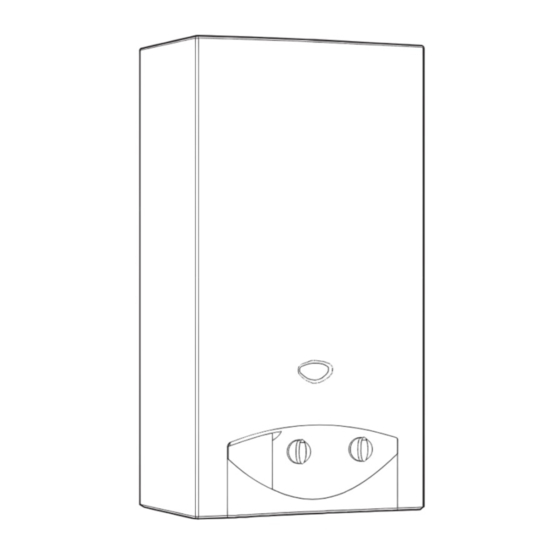
6 | Technical Characteristics and Dimensions Special accessories • Conversion kit from natural gas to butane/propane. Dimensions Fig. 1 Front cover Gas connection Hole for fixing to wall Flue socket Temperature control Draught diverter with flue gas monitor Led indicator for battery charge level Heat exchanger ON/OFF switch Automatic gas valve... -
Page 7: Functional Diagram Of The Heater
Technical Characteristics and Dimensions | 7 Functional diagram of the heater Fig. 2 Functional diagram Pilot burner Gas inlet Igniter electrode Gas filter Ionisation detector Battery compartment Heat exchanger Hot water pipe Main burner Igniter unit Injector Led indicator for burner status Testing point for burner pressure ON/OFF switch Testing point for supply pressure... -
Page 8: Electrical Diagram
8 | Technical Characteristics and Dimensions Electrical diagram Fig. 3 Electrical diagram Servo valve (normally open) Igniter unit Diaphragm valve LED indicator for battery charge level Main valve (normally closed) LED indicator for burner status Ionisation detector ON/OFF switch Igniter electrode Batteries, 1.5V Flue gas safety device Microswitch... -
Page 9: 2.11 Technical Characteristics
Technical Characteristics and Dimensions | 9 2.11 Technical characteristics Technical characteristics Symbol Units WR11 WR14 WR18 Power and flow Nominal useful power Btu/h 65570 80595 104165 Minimum useful power Pmin Btu/h 23905 23905 23905 Useful power (adjustment range) Btu/h 23905-65570 23905 - 80595 23905 - 104165 Nominal thermal flow... -
Page 10: Use
10 | Use Open all water and gas blocking devices. Purge the pipes. CAUTION: The front panel in the burner and pilot burner area may reach high temperatures, with risk of burning in case of contact Before starting up the heater 6720680412-01.1av CAUTION: Fig. -
Page 11: Power Adjustment
Use | 11 Turning off Regulating the temperature to the minimum required value reduces energy consumption as well as the B Press the switch , position possibility of limescale deposits in the heat exchanger. Power adjustment Purge the appliance Lower water temperature. If there is a risk of freezing, proceed as follows: Less power. -
Page 12: Regulation
12 | Regulation Regulation Any local by-laws and regulations pertaining to installation and use of gas-heated appliances must be observed. Please refer to the laws that should be attended in South Africa. 6 720 648 592 (2011/06) -
Page 13: Installation (Must Be Carried Out Only By Qualified Technicians)
Installation (must be carried out only by qualified technicians) | 13 Installation (must be carried out only by qualified technicians) • To avoid corrosion, the combustion air must be free DANGER: Explosion! from harmful substances. Examples of particularly B Always turn off the gas cock before corrosive substances: halogenated hydrocarbons carrying out any work on components contained in solvents, paints, glues, engine gases and... -
Page 14: Heater Mounting
14 | Installation (must be carried out only by qualified technicians) – be thermally insulated Water connection – have an exit above the maximum roof level. It is advisable to purge the installation beforehand, • The combustion gases evacuation pipe must be because the presence of dirt may reduce the flow and, inserted in the flue ring. -
Page 15: Inlet/Exhaust Pipe Installation
Installation (must be carried out only by qualified technicians) | 15 Any local by-laws and regulations pertaining to installation and use of gas-heated appliances must be observed. Please refer to the laws that should be attended in your country. Inlet/exhaust pipe installation Pipes should be installed according to the instructions in the relevant manual. -
Page 16: Adjustments (Must Be Carried Out Only By Qualified Technicians)
16 | Adjustments (must be carried out only by qualified technicians) Adjustments (must be carried out only by qualified technicians) B Connect the pressure gauge to the measuring point Factory regulations for the burner pressure. Sealed parts must not be interfered with. Natural gas Heaters designed for Natural gas H (G 20) are factory sealed for delivery after the values on the characteristics... -
Page 17: Conversion To A Different Type Of Gas
Adjustments (must be carried out only by qualified technicians) | 17 Natural gas H Butane Propane 8708202113 8708202130 (1,10) (0,70) WR11 8708202124 8708202128 (1,20) (0,72) 8708202113 8708202128 (1,10) (0,72) Injector code WR14 8708202116 8708202132 (1,25) (0,75) 8708202115 8708202130 (1,15) (0,70) WR18 8708202116 8708202132... -
Page 18: Maintenance (Must Be Carried Out Only By Qualified Technicians)
Water filter basis (inspection) or if necessary (maintenance). B Replace the water filter installed in the water valve These jobs can only be done by a Bosch Technical entry. Assistance delegate. WARNING:... - Page 19 Maintenance (must be carried out only by qualified technicians) | 19 B Undo magnetic unit connector. B Remove thermocouple. B Replace damaged component with new one and refit using the reverse of the procedure set out in the table above. Function check Flue gas safety device function check: B Disconnect flue pipe;...
-
Page 20: Problems
20 | Problems Problems Assembly, maintenance and repairs must be performed by qualified technicians only. The following chart offers solutions to possible problems (solutions followed by an * must be undertaken by qualified technicians only). Problem Cause Solution The heater does not ignite. Switch turned off. -
Page 21: Environment / Disposal
Environment / disposal | 21 Environment / disposal Environmental protection is a fundamental corporate strategy of the Bosch Group. The quality of our products, their economy and environmental safety are all of equal importance to us and all environmental protection legislation and regulations are strictly observed. - Page 22 22 | Environment / disposal Notes 6 720 648 592 (2011/06)
- Page 23 Environment / disposal | 23 Notes 6 720 648 592 (2011/06)
- Page 24 6720648592 B/S/H/ Home Appliances Private Bag X36 Randjespark Halfway House 1685 Visitors: Fifteenth Road Randjespark Midrand Tel: (011) 265-7800 Fax: (011) 265-7817 www.boschappliances.co.za...
Need help?
Do you have a question about the WR11B series and is the answer not in the manual?
Questions and answers