Table of Contents
Advertisement
Quick Links
Installation and Operating Instructions
Gas Instantaneous Water Heater
Safety instructions:
If you smell gas:
- Do not operate any electrical switches.
- Do not telephone from inside the danger area.
- Turn off the gas cock.
- Open windows and ventilate room.
- From outside, call the gas company and your approved
installer.
Do not use or store easily combustible materials in the vicinity
of the appliance.
WR10..B...
WR11..B...
With electronic ignition and triple safety system
consisting of ionisation detector, flue gas monitor
and heat exchanger temperature sensor.
Installation and servicing of the appliance may only be
carried out by an approved technician.
The appliance should be regularly serviced in order to ensure
that it remains in perfect and safe working order.
If there is a risk of freezing, the appliance must be switched
off and drained. If the appliance has not been drained during
a cold spell, when it is switched on again check that it
produces hot water. If problems occur, contact your installer
Advertisement
Table of Contents

Related Manuals for Bosch WR10**B SERIES


Summary of Contents for Bosch WR10**B SERIES
- Page 1 Installation and Operating Instructions Gas Instantaneous Water Heater WR10..B... WR11..B... With electronic ignition and triple safety system consisting of ionisation detector, flue gas monitor and heat exchanger temperature sensor. Safety instructions: Installation and servicing of the appliance may only be carried out by an approved technician.
-
Page 2: Table Of Contents
Contents Technical Characteristics and Dimensions 2.5 Gas connection ..............5 1. 1 Category, Appliance Type and Approval Number ..2 2.6 Flue ..................5 1.2 General Description ............2 2.7 Commissioning ..............6 1.3 Explanation of Model Code ..........2 1.4 Dimensions ................. -
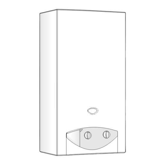
Page 3: Dimensions
Dimensions 1. Front cover 2. Hole for fixing to wall 3. Observation window 4. Temperature control 5. LED indicator for battery charge level 6. On/Off switch 7. Output control 8. Gas connection 9. Flue socket 10. Draught diverter with flue gas monitor 11. -
Page 4: Circuit Diagram
Circuit diagram Servo valve (normally open) Diaphragm valve Main valve (normally closed) Ionisation detector Igniter electrode Flue gas safety device Temperature limiter Igniter unit LED indicator for battery charge level LED indicator for burner status On/Off switch Batteries, 1.5 V Microswitch Fig. -
Page 5: Regulations
Preconditions for installation in extreme cases, could completely clog up the appliance. Mark hot water (fig.5,pos.B) and cold water pipes (fig.5, The appliance can only be sold in the countries mentioned pos.A) so as to prevent confusion. in the type plate. Connect pipe to automatic water valve using the connecting kit supplied. -
Page 6: Commissioning
Check the gas and water valves for leaks and carry out a complete function check. Sealed parts must not be interfered with. If components need to be replaced, use only genuine Bosch spare parts. 3. 1 Function... -
Page 7: Converting To A Different Gas Type
* This work may only be carried out by an approved engineer. Converting to a different gas type Use only the genuine Bosch conversion kit. Conversion may only be carried out by an approved technician. Troubleshooting Installation, servicing and repairs may only be carried out by an approved engineer. -
Page 8: Operation
Operation Turn on all gas and water taps Purge air from pipes If the red LED starts flashing, Insert two 1.5 V type R 20 batteries replace batteries in battery compartment Safety precautions for use of batteries: - Do not dispose of batteries with normal household waste, take them to a recycling site instead.
Need help?
Do you have a question about the WR10**B SERIES and is the answer not in the manual?
Questions and answers