Table of Contents
Advertisement
Order parts online
www.follettice.com
Cool Ideas For Ice Management
Installation, Operation and Service Manual
Following installation, please forward this manual
to the appropriate operations person.
801 Church Lane • PO Box D, Easton, PA 18044, USA
Toll free (800) 523-9361 • (888) 2-FOLLETT
(610) 252-7301 • Fax (610) 250-0696 • www.follettice.com
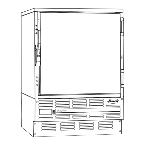
Undercounter Refrigerator
Before service number B59000
REF Series
U L
U L
®
C
®
00104109R09
Advertisement
Table of Contents

Related Manuals for Follett Symphony REF Series


Summary of Contents for Follett Symphony REF Series
- Page 1 Following installation, please forward this manual to the appropriate operations person. 801 Church Lane • PO Box D, Easton, PA 18044, USA Toll free (800) 523-9361 • (888) 2-FOLLETT Cool Ideas For Ice Management (610) 252-7301 • Fax (610) 250-0696 • www.follettice.com ®...
- Page 2 A return authorization number has been issued by customer service within 30 days after shipment. Follett receives the equipment at the factory in Easton, PA within 30 days after issuance of the return authorization number. The equipment must be returned in Follett packaging. If the packaging has been damaged or discarded, Follett will forward, at the customer’s expense, new packaging.
-
Page 3: Table Of Contents
Welcome to Follett........ -
Page 4: Welcome To Follett
Before you begin After uncrating and removing all packing material, inspect the equipment for concealed shipping damage. If damage is found, notify the shipper immediately and contact Follett Corporation so that we can help in the filing of a claim, if necessary. -
Page 5: Installation Procedures
Installation Leveling the refrigerator Internal stabilizing legs are provided to level the refrigerator in its final location. These legs are retracted for shipping. To allow the refrigerator to slide easily during installation the stabilizing legs can be extended to clear the bottom of the refrigerator panels. -
Page 6: Changing The Temperature Set Point
Changing the temperature set point Follett sets the temperature controller to a 38˚F set point. This set point may not deliver the temperature range desired for your specific application. For example, some medicine manufacturers suggest a storage temperature range of 36˚ to 46˚F. Therefore, we have provided you with the ability to easily change the set point to meet your specific needs. -
Page 7: Operation
Operation How the refrigerator works The temperature control board and probe indicate when the refrigeration system is required to turn on and off. The probe signals the controller to turn the refrigeration system on when the interior cabinet temperature rises to the controller set point. -
Page 8: Service Information
Adjust latch and or striker as necessary for proper door closure. Fig. 8 Slide-out compressor tray Follett's slide-out compressor tray allows technicians to partially slide the condensing unit from the refrigerator back without cutting refrigerant lines. 1. Remove the rear panel (Fig. 8.1) 2. -
Page 9: Refrigeration System Diagram
This change can adversely affect the performance of your refrigerator. Therefore, Follett recommends that if hoses are ever connected to the refrigeration system for service, the refrigerant should be recovered, the system evacuated, and recharged by weighing in the correct refrigerant charge. -
Page 10: Troubleshooting Guide
5. Recover, evacuate and weigh in correct charge. 6. Plugged capillary tube. 6. Replace capillary tube. 7. Inefficient compressor. 7. Consult technical service. If problems persist after following this basic troubleshooting guide, call Follett’s technical service group at (800) 523-9361, (888) 2-FOLLETT or (610) 252-7301. -
Page 11: Accessory Information
Accessories Temperature alarm Fig. 9 Before installing alarm 1. Remove supplied 9-volt back-up battery from packing box. 2. Remove 2 screws from module face and remove faceplate. 3. Install back-up battery on battery connector. 4. Locate DIP switches on the back of the faceplate (Fig. -
Page 12: Pyxis
6. Route probe through hole in refrigerator back and push Fig. 12 probe down through gasketed bottle top. Note: Alarm probe must be placed in bottle for Power proper system operation. Refer to Fig. 12 if attaching alarm to central monitoring or central alarm system. A SPDT 1 amp 24V AC resistive relay is provided for this Black connection. -
Page 13: Replacement Parts
Replacement parts Condensing unit - Reference #11 Evaporator - Reference #5 Refrigeration Reference # Description Part # Fan motor, evaporator 00104919 Bracket, fan motor 00104927 Fan blade 00104935 Fan guard 00104943 Evaporator (includes parts above) 00104885 Filter drier & capillary tube 00103267 Compressor 00104950... - Page 14 rear cutaway 20 24 Hardware Reference # Description Part # Door, REF5 (includes gasket) 00105015 Not shown Door, REF4-ADA (includes gasket) 00113910 Latch & striker (includes screws) 00105023 Latch screws (each – 3 per latch) 00103507 Striker screws (each – 2 per striker) 502287 Hinge (each –...
- Page 15 Temperature alarm accessory Reference # Description Part # Not shown Bottle kit (includes bottle, bracket and gasket) 00113779 Not shown Controller kit (includes battery, probe and power supply) 00108175 Not shown Gasket, bottle 00112029 Not shown Bracket, bottle 00112011 Not shown Bottle 00112037 Not shown...
- Page 16 801 Church Lane • PO Box D, Easton, PA 18044, USA 00104109R09 Toll free (800) 523-9361 • (888) 2-FOLLETT Cool Ideas For Ice Management 02/05 (610) 252-7301 • Fax (610) 250-0696 • www.follettice.com ® ®...
Need help?
Do you have a question about the Symphony REF Series and is the answer not in the manual?
Questions and answers