Table of Contents

Subscribe to Our Youtube Channel
Related Manuals for Dimplex DFP6975O


Summary of Contents for Dimplex DFP6975O
- Page 1 ELECTRIC FIREPLACE MODEL #DFP6975O Français p. 23 Español p. 45 Questions, problems, missing parts? Before returning to your retailer, call our customer service department at 1-888-346-7539, 8 a.m.- 4:30 p.m., EST, Monday-Friday.
-
Page 2: Table Of Contents
TABLE OF CONTENTS Safety Information ......................... Package Contents ......................... Hardware Contents ....................... Preparation ..........................Unpacking Instructions - Firebox ................... Assembly Instructions - Firebox ................... Assembly Instructions - Mantel .................... Installation Instructions ......................Operation Instructions ......................Care and Maintenance ......................Troubleshooting ........................ -
Page 3: Safety Information
SAFETY INFORMATION Please read and understand this entire manual before attempting to assemble, operate or install the product. If you have any questions regarding the product, please call customer service at 1-888-346-7539, 8 a.m.- 4:30 p.m., EST, Monday-Friday. 1. This fireplace is hot when in use. To avoid burns, do not let bare skin touch hot surfaces. The trim around the heater outlet becomes hot during heater operation. - Page 4 SAFETY INFORMATION SAVE THESE INSTRUCTIONS Procedures and techniques that are considered important enough to emphasize. CAUTION: Procedures and techniques which, if not carefully followed, will result in damage WARNING: to the equipment. Procedures and techniques which, if not carefully followed, will expose the user DANGER: to the risk of fire, serious injury, illness or death.
-
Page 5: Package Contents
PACKAGE CONTENTS Part Description Quantity Part Description Quantity Mantel Hearth Mantel Top Mantel Side, LH Firebox Mantel Side, RH Firebox Front Glass Mantel Header Firebox Remote Control... -
Page 6: Hardware Contents
HARDWARE CONTENTS Picture Picture Description Description Part Quantity Part Quantity (Shown to size) (Shown to size) Wing Bolt Wood Dowel PREPARATION Before beginning assembly of product, make sure all parts are present. Compare parts with package contents list and diagram above. If any part is missing or damaged, do not attempt to assemble the product. -
Page 7: Unpacking Instructions - Firebox
UNPACKING INSTRUCTIONS - FIREBOX Fig. 1 Once the firebox is removed from the carton, a protective foam block that keeps the ember bed assembly in place will need Foam Block to be removed. 1. Gently pull the foam block out from the firebox and discard (Fig. -
Page 8: Assembly Instructions - Firebox
ASSEMBLY INSTRUCTIONS - FIREBOX Fig. 2 The only assembly required for the firebox is to install the front glass. 1. Remove the right hand side trim piece from the firebox (F) by removing three (3) Philips head screws as shown in Fig. 2. Screws (2) 2. -
Page 9: Assembly Instructions - Mantel
ASSEMBLY INSTRUCTIONS - MANTEL Fig. 4 1. Insert 2 wood dowels (BB) into hearth (A) as shown in Fig. 4 Hardware Used Wood Dowel Fig. 5 2. Lower right side panel (C) and left side panel (B) onto wood dowels (BB) and hearth (A) as shown in Fig. - Page 10 ASSEMBLY INSTRUCTIONS - MANTEL 3. Position header (D) as shown in Fig. 6 and Fig. 6 lower onto biscuits of right side panel (C) and left side panel (B). 4. Secure header (D) to assembly with 4 Fig. 7 wing bolts (AA). (Fig. 7) Hardware Used Wing Bolt...
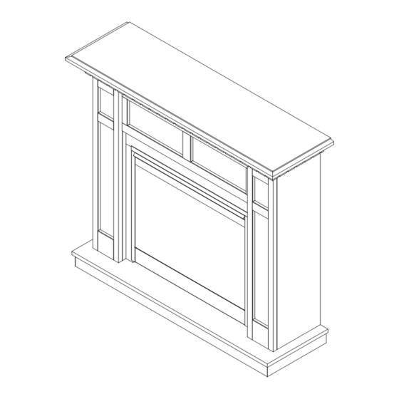
- Page 11 ASSEMBLY INSTRUCTIONS - MANTEL 5. Position top (E) as shown in Fig. 8, lower Fig. 8 onto assembly and secure with 4 wing bolts (AA). Hardware Used Wing Bolt 6. Insert firebox (F) into fully assembled Fig. 9 mantel as shown in Fig. 9 and route power cord through the back of the mantel.
-
Page 12: Installation Instructions
INSTALLATION INSTRUCTIONS Ensure the power cord is not installed so that it is pinched or against any sharp DANGER: edges and ensure that the power cord is stored or secured to avoid tripping or snagging to reduce the risk of fire, electric shock or injury to persons. Electrical outlet wiring must comply with local building codes and other applicable regulations to reduce the risk of fire, electric shock and injury to persons. -
Page 13: Operation Instructions
OPERATION INSTRUCTIONS Electric Fireplace/Firebox Manual Control The manual controls for the fireplace are behind the access panel located at the bottom of the firebox. (Fig. 10) Fig. 10 1. Main ON/OFF Switch - The ON/OFF Switch supplies power to all fireplace functions. 2. - Page 14 OPERATION INSTRUCTIONS Remote Control Fig. 11 The fireplace is supplied with a radio frequency firebox remote control (H). This firebox remote control has a range of approximately 50 feet (15.25 m), it does not have to be pointed at the fireplace and can pass through most obstacles (including walls).
-
Page 15: Care And Maintenance
CARE AND MAINTENANCE Disconnect the power before attempting any maintenance or cleaning to reduce WARNING: the risk of fire, electric shock or damage to property and bodily harm to persons. Light Bulb Replacement The light bulbs need to be replaced when you notice a dark section of the flame or when the clarity and detail of the ember bed assembly exterior reduces. - Page 16 CARE AND MAINTENANCE Lower Light Bulb Requirements Quantity of 3 clear chandelier or candelabra bulbs with an E-12 (small) socket base, 60 watt rating. Example: GE 60BC or Philips 60 CTC. DO NOT EXCEED 60 WATTS PER BULB CAUTION: Fig. 12 To access the lower light bulb area: 1.
- Page 17 CARE AND MAINTENANCE Upper Light Bulb Requirements Quantity of 2 clear chandelier or candelabra bulbs with an E-12 (small) socket base, 15 watt rating. DO NOT EXCEED 15 WATTS PER BULB CAUTION: To access the upperlight bulb area: 1. Slide fireplace out of mantel. 2.
-
Page 18: Troubleshooting
TROUBLESHOOTING Problem Possible Cause Corrective Action Circuit breaker trips 1. Short in unit wiring. 1. Trace wiring in unit. or fuse blows when 2. Improper circuit current rating. 2. Additional appliances may exceed unit is turned on. the current rating of the circuit breaker or fuse. - Page 19 TROUBLESHOOTING Problem Possible Cause Corrective Action Heater is not turning 1. Improper operation. 1. Refer to instruction manual. 2. Defective heater on/o switch. 2. Replace heater on/o switch. 3. Loose wiring. 3. Trace wiring in unit. 4. Defective remote control. 4.
-
Page 20: Warranty
WARRANTY Two Year Limited Warranty Products to which this limited warranty applies This limited warranty applies to your newly purchased electric fireplace. This limited warranty applies only to purchases made in any province of Canada except for Yukon Territory, Nunavut, or Northwest Territories or in any of the 50 States of the USA (and the District of Columbia) except for Hawaii and Alaska. - Page 21 WARRANTY What the manufacturer will do in the event of a defect In the event a product or part covered by this limited warranty is proven to be defective in material or workmanship during (i) the 2 year limited warranty period for products other than fireplace surrounds (mantels) and trims, and (ii) the 1 year limited warranty period for surrounds (mantels) and trims, you have the following rights: •...
-
Page 22: Replacement Parts List
REPLACEMENT PARTS LIST For replacement parts, call our customer service department at 1-888-346-7539, 8 a.m.- 4:30 p.m., EST, Monday-Friday. Part Description Part # Hearth DFP6975O-HRTH Header DFP6975O-HDR Side LH DFP6975O-L Side RH DFP6975O-R DFP6975O-TOP Ember Bed Assembly 0437960100RP Flicker Motor...
Need help?
Do you have a question about the DFP6975O and is the answer not in the manual?
Questions and answers