Dimplex DFI2309 Service Manual
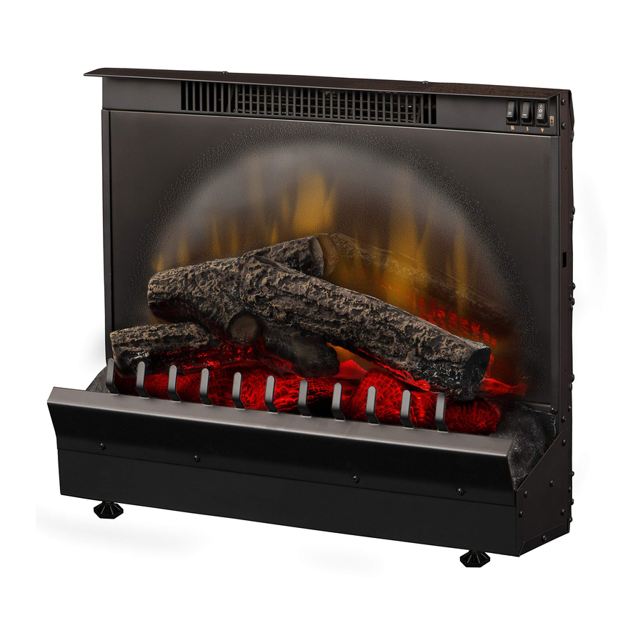
23” insert
Hide thumbs
Also See for DFI2309:
- Parts and service manual (17 pages) ,
- Owner's manual (16 pages) ,
- Practical user's manual (11 pages)
Table of Contents
Advertisement
Service Manual
23" Insert
Model Numbers:
DFI2309 MOD ~ to D
DFI2310 MOD ~ to D
Dimplex North America Limited
1367 Industrial Road
Cambridge ON Canada N1R 7G8
1-888-346-7539
www.dimplex.com
In keeping with our policy of continuous product development, we reserve the right to make changes without notice.
Rev
PCN
Date
00
n/a
10.2006
01
12226
08.2010
02
13569
09.2012
7400070000R02
Advertisement
Table of Contents

Related Manuals for Dimplex DFI2309


Summary of Contents for Dimplex DFI2309
- Page 1 Service Manual 23” Insert Model Numbers: DFI2309 MOD ~ to D DFI2310 MOD ~ to D Date 10.2006 12226 08.2010 13569 09.2012 Dimplex North America Limited 1367 Industrial Road Cambridge ON Canada N1R 7G8 1-888-346-7539 www.dimplex.com In keeping with our policy of continuous product development, we reserve the right to make changes without notice.
-
Page 2: Table Of Contents
DFI2309 MOD C to D ........ -
Page 3: Operation
(Figure 1-A or B) to the Off (“ O ”) position, and waiting five (5) minutes before switching the unit back on. CAUTION: If you need to continuously reset the heater, unplug the unit and call Dimplex North America Limited at 1-888-346-7539 for technical support. Heat Switches (all models, all MOD levels) Figure 1-C - Low Heat Switch (“... - Page 4 (including walls). It is Used in: supplied with one of 243 independent frequencies to prevent • DFI2309 MODs C to D interference with other units and the frequency designation is • DFI2310 MOD A2 to D indicated on the back of the remote control.
-
Page 5: Exploded Parts Diagram
Exploded Parts Diagram... -
Page 6: Replacement Parts List
Replacement Parts List DFI2309 - Part Number ....6901470159 DFI2310 - Part Number ....6901470259 Replacement Parts for both DFI2309, DFI2310 all MODs: 1. -
Page 7: Wiring Diagram
Wiring Diagram DFI2309 MOD ~ to B Blower Terminal Block Cutout Power Cord Heater Elements High Heat Switch Main Low Heat Switch On/Off Switch Terminal Block Lamp holders Flicker Motor... -
Page 8: Dfi2309 Mod C To D
Wiring Diagram DFI2309 MOD C to D Blower Terminal Block Remote Cutout Control Receiver Power Cord Heater Elements High Heat Switch Main On/Off/On Low Heat Switch Switch Terminal Block Lamp holders Flicker Motor... -
Page 9: Dfi2310 Mod
Wiring Diagram DFI2310 MOD ~ Blower Wire Harness to Log Set LED Log Set Terminal Block Driver Cutout Power Cord Heater Elements High Heat Switch Low Heat Switch Main On/Off Switch Terminal Block Lamp holders Flicker Motor... -
Page 10: Dfi2310 Mod A To D
Wiring Diagram DFI2310 MOD A to D Blower LED Log Set Driver Wire Harness to Log Set Remote Cutout Receiver Board Terminal Block Cord Set Heater Elements High Heat Switch Low Heat Switch Main On/Off/On Switch Terminal Block Lamp holders Flicker Motor... -
Page 11: Universal Replacement Procedures
Universal Replacement Procedures Figure 5 Switch control panel Partially Reflective Glass Replacement Partially reflective If the firebox was operating prior to servicing allow at least glass five (5) minutes for light bulbs and heating element to cool off Log set to avoid accidental burning of skin. -
Page 12: Heater Assembly/Cutout Replacement
within the firebox. Be sure to note each wire’s original Figure 7 location carefully. Step 5 screws to remove (4) 5. Remove the switch by depressing the retaining clips Top cover (Figure 6) and pushing the switch forward, through the sheet metal of the firebox. -
Page 13: Power Cord Replacement
Power Cord Replacement ii) Remove the two (2) piggy-back and three (3) single wire connectors from the heater element and motor, noting If the firebox was operating prior to servicing allow at least their original locations. five (5) minutes for light bulbs and heating element to cool off iii) Remove the two (2) Phillips screws from each of the to avoid accidental burning of skin. -
Page 14: Model / Mod Specific Procedures
NOTE: If Flicker Rod is bent out of alignment, carefully bend it back to become straight. If Flicker Rod is not DFI2309 & DFI2310 MODs ~ to C properly aligned, it may cause noise during operation by rubbing against metal chassis. -
Page 15: Flicker Motor/Flicker Rod Replacement
Ensure that Replacement Procedure for: connections to/from Flicker Motor match those of the DFI2309 & DFI2310 MODs ~ to C respective wiring diagram for the particular model and MOD level being serviced (pages 7-10). -
Page 16: Remote Receiver Board Replacement
Remote Control Receiver Replacement Cover screw DFI2309/2310 MODs C to D If the fireplace was operating prior to servicing allow at least five (5) minutes for light bulbs and heating element to cool off to avoid accidental burning of skin. -
Page 17: Light Harness Replacement
Replacement Procedure for: DFI2309 & DFI2310 MODs ~ to C 1. Disconnect power and remove firebox from mantel or existing fireplace. 2. Remove the two (2) outer Phillips screws on the log grate at the front of the firebox as shown in Figure 11. -
Page 18: Log Driver Board Replacement
If the fireplace was operating prior to servicing allow at least Replacement Procedure for: five (5) minutes for light bulbs and heating element to cool off DFI2309 & DFI2310 MODs D to avoid accidental burning of skin. Disconnect power before attempting any maintenance or 1. - Page 19 Figure 21 Log Driver Board back panel and just under the terminal block (Figure 21). 7. Either pinch the clasp to release or cut each of the four (4) mounting studs (one in each corner of the Log Driver Board) that attach the circuit board to the chassis of the firebox.
-
Page 20: Troubleshooting Guide
Troubleshooting Guide PROBLEM CAUSE SOLUTION General Circuit breaker trips or fuse Short in unit wiring. Trace wiring in unit. blows when unit is turned on Improper circuit current rating Additional appliances may exceed the current rating of the circuit breaker or fuse. Plug unit into another outlet or install unit on a dedicated 15 amp circuit. - Page 21 PROBLEM CAUSE SOLUTION Heater Heater is not turning off Improper operation Refer to Operation Section Defective Heater Switches Replace Heater Switch(es) Heater is not turning on, but Improper operation Refer to Operation Section flame effect is still functioning Loose wiring Trace wiring in unit.
Need help?
Do you have a question about the DFI2309 and is the answer not in the manual?
Questions and answers