Sign In
Upload
Download
Table of Contents
Contents
Add to my manuals
Delete from my manuals
Share
URL of this page:
HTML Link:
Bookmark this page
Add
Manual will be automatically added to "My Manuals"
Print this page
×
Bookmark added
×
Added to my manuals
Manuals
Brands
AUDAC Manuals
Amplifier
COM12
User manual & installation manual
AUDAC COM12 User Manual & Installation Manual
Public address amplifier
Hide thumbs
1
2
Table Of Contents
3
4
5
6
7
8
9
10
11
12
13
14
15
16
17
page
of
17
Go
/
17
Contents
Table of Contents
Bookmarks
Table of Contents
User Manual
Installation Guide
Table of Contents
Introduction
Environment
Safety Requirements
Caution - Servicing
Pin Connections on Connectors
Overview Front and Rear Panel of the Com12/Com24 (same for the Com24)
Front
Rear
Overview Input Controls (same for the Com24)
Input 1 - 6 (Front)
Overview Output Controls (same for the Com24)
Output 1-5 ( Front )
Overview Input Section Line Inputs (same for the Com24)
Input 1-6 (Rear)
Overview Input Section Tele-Paging and Remote MIC (same for the Com24)
Overview Cascading Ports (same for the Com24)
Cascading Ports (Rear)
Overview Output Section (same for the Com24)
Getting Started
Priority Settings
Phantom Power
Telephone Paging
Connecting External Equipment
Cascading Com12/Com24 Public Address Amplifiers
Connecting the Speakers
Wire up the System
Additional Information Com12/Com24
Technical Specifications
Personal Notes
Advertisement
Quick Links
1
User Manual
2
Installation Guide
3
Pin Connections on Connectors
4
Connecting the Speakers
5
Wire up the System
6
Technical Specifications
Download this manual
Public Address Amp
COM12/COM24
AUDAC
PROFESSIONAL AUDIO EQUIPMENT
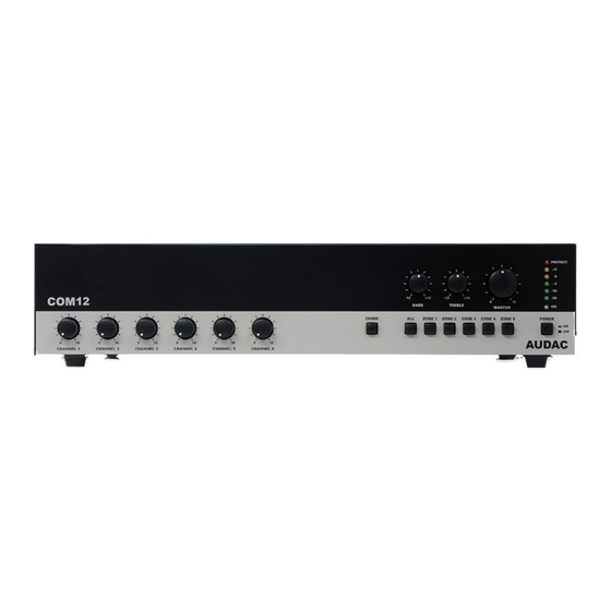
Public Address Amplifier COM12/COM24
User Manual &
Installation Guide
Table of
Contents
Previous
Page
Next
Page
1
2
3
4
5
Advertisement
Table of Contents
Need help?
Do you have a question about the COM12 and is the answer not in the manual?
Ask a question
Questions and answers
Related Manuals for AUDAC COM12
Amplifier Audac CAP412 User Manual & Installation Manual
Four channel 100v power amplifier (15 pages)
Amplifier Audac CAP248 User Manual
Cap series professional 100v multi-channel power amplifiers (16 pages)
Amplifier Audac CAP448 User Manual
Cap series professional 100v multi-channel power amplifiers (16 pages)
Amplifier Audac CAP224 User Manual
Cap series professional 100v multi-channel power amplifiers (16 pages)
Amplifier Audac CAP424 User Manual
Cap series professional 100v multi-channel power amplifiers (16 pages)
Amplifier AUDAC COM12 Mk2 User Manual
Public address amplifiers (20 pages)
Amplifier AUDAC COM24 Mk2 User Manual
Public address amplifiers (20 pages)
Amplifier AUDAC CPR12 User Manual & Installation Manual
Preamplifier (17 pages)
Amplifier AUDAC COM24 User Manual & Installation Manual
Public address amplifier (17 pages)
Amplifier AUDAC CPA12 User Manual & Installation Manual
(55 pages)
Amplifier AUDAC CPA24 User Manual & Installation Manual
Professional audio equipment (14 pages)
Amplifier AUDAC COM104 User Manual
(16 pages)
Amplifier AUDAC COM108 User Manual
(16 pages)
Amplifier AUDAC CEP Series Quick Start Manual
Multi-zone amplifier (4 pages)
Amplifier AUDAC M1 User Manual & Installation Manual
Multimedia amplifier (28 pages)
Amplifier Audac R1 User Manual & Installation Manual
Multi-room amplifier (35 pages)
This manual is also suitable for:
Com24
Table of Contents
Print
Rename the bookmark
Delete bookmark?
Delete from my manuals?
Login
Sign In
OR
Sign in with Facebook
Sign in with Google
Upload manual
Upload from disk
Upload from URL


Need help?
Do you have a question about the COM12 and is the answer not in the manual?
Questions and answers