
Related Manuals for AUDAC CPR12


Summary of Contents for AUDAC CPR12
- Page 1 Preamplifier CPR12 AUDAC PROFESSIONAL AUDIO EQUIPMENT CPR12 Preamplifier User Manual & Instal l a ti o n Guide...
- Page 2 A U D A C P R O F E S S I O N A L A U D I O E Q U I P M E N T User Manual & Installation Guide AUDAC http://www.audac.eu info@audac.eu...
-
Page 3: Table Of Contents
Index INTRODUCTION ............................................3 ENVIRONMENT .............................................4 SAFETY REQUIREMENTS..........................................5 CAUTION – SERVICING ..........................................5 OVERVIEW FRONT AND REAR PANEL OF THE CPR12..............................6 FRONT ................................................6 REAR ................................................6 DETAILS FRONT AND REAR PANEL OF THE CPR12...............................7 FRONT PANEL .............................................7 REAR PANEL..............................................9 CONNECTIONS ............................................11 CONNECTOR AND CABLE CONFIGURATION ..................................12 BLOCK DIAGRAM ............................................14... -
Page 4: Introduction
Delivering a flexible audio solution to control multiple functions Easy to use Excellent sound quality Modern and advanced design The CPR12 can be used in commercial applications such as restaurants, hotels, shops, warehouses, professional offices, public buildings, … 3 3 3 3... -
Page 5: Environment
Chapter Environment Do not place this unit in an enclosed environment such as a bookshelf or closet. Ensure that there is adequate ventilation to cool the unit. Do not block the ventilation openings. Do not place the unit in environments which contain high levels of dust, heat, moisture or vibration. -
Page 6: Safety Requirements
Only use a grounded socket outlet and a power cord with grounding plug to plug in the unit. This unit is not a toy. It should not be operated by children. Do not stick objects through the openings of the CPR12. Do not open the unit (risk for electrical shock). CAUTION – SERVICING This unit contains no user serviceable parts. -
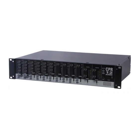
Page 7: Overview Front And Rear Panel Of The Cpr12
Chapter Overview front and rear panel of the CPR12 FRONT PANEL REAR PANEL 6 6 6 6... -
Page 8: Details Front And Rear Panel Of The Cpr12
Details front and rear panel of the CPR12 Details Details Details FRONT PANEL 1 2 3 9 11 13 15 1. Trim Controls These controls allow variable input level. They have 44dB adjustable ranges - 60dB to -16dB for microphone level and -30dB to +14dB for line level. - Page 9 6. PFL Switches This switch allows you to monitor the pre-fader signal of the input channel through the monitor speaker. 7. Output Channel Selectors These selectors allow each input signal to be routed to the selected output channel. 8. Output Channel EQ Controls Output channels have 2 bands equalizers which are adjustable over a wide range.
-
Page 10: Rear Panel
REAR PANEL 1. DC 24V Input and Link Output The device will be supplied by the DC 24V input terminal and will supply power to other devices by the link output terminal. 2. AC Inlet This AC inlet (230V, 50Hz) allows you to replace the fuse conveniently. Please check the value of the fuse before replacement. - Page 11 4. Sub Output The sub amplifier will be connected to this output terminal. The output signal is a fixed level signal. 5. Main Output The main amplifier will be connected to this output terminal. 6. Priority Input All input signals will be muted automatically by the priority input signal. This terminal will be used for evacuation announcement.
-
Page 12: Connections
Chapter Connections AUDAC products are wired to reflect accepted wiring practices used throughout the world. Balanced XLR connectors are wired as described: Pin #1 Shield Pin #2 Positive Pine #3 Negative Balanced 1/4” TRS connectors are wired as described: Tip is Positive... -
Page 13: Connector And Cable Configuration
CONNECTOR AND CABLE CONFIGURATION Connector and cable configurations recommended for use with the CPR-series. These cables are based on the use of auxiliary equipment that is isolated from the AC power mains. -
Page 15: Block Diagram
Block diagram... -
Page 16: Additional Information Cpr12
Chapter Additional information CPR12 TECHNICAL SPECIFICATIONS Balanced Master Output 0dBm Rated Output Voltage Unbalanced Sub Output 0dBm Unbalanced Rec output -10dBm Balanced Microphone -60dBm channels Balanced Line 1-6 channels -30dBm Input sensitivity for rated output Unbalanced Line 7-10 -30dBm at maximum gain... -
Page 17: Personal Notes
Personal notes...
Need help?
Do you have a question about the CPR12 and is the answer not in the manual?
Questions and answers