CODELOCKS CL5020 Installation Manual
Hide thumbs
Also See for CL5020:
- Installation instructions manual (11 pages) ,
- Getting started manual (20 pages)
Advertisement
You are currently in: Codelocks UK > CL5020 Lock Installation Guide
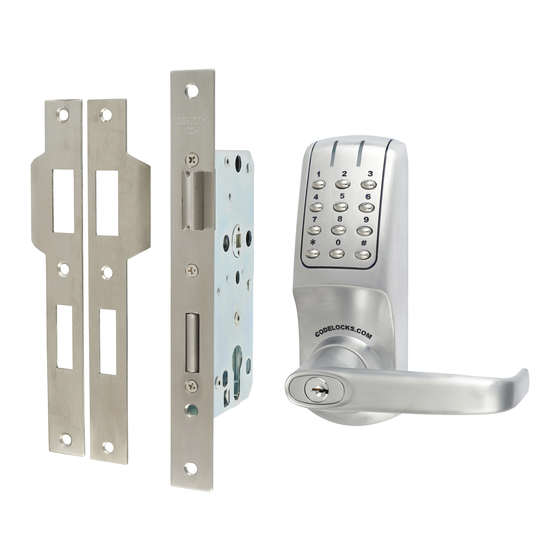
CL5020 Installation Guide
.
Number relating to picture
1
2
3
4
5
6
7
8
9
10
11
12
13
14
Not in parts drawing
Tools Required
Power Drill
Drill bits 0 19, 12, 16 & 20mm
Philips screwdriver
Hammer / mallet
Chisel 25mm
Stanley knife
Adhesive tape, pencil, bradawl, tape measure
Drill bits 25, 16, 12 & 10mm
Pliers and hacksaw for cutting bolts
Operations Check
You should familiarise yourself with the operation of the lock and check that all parts work properly.
Remove the battery cover from the back plate and install the 4 x AA cells.
Connect the cables from the front plate and back plate. A bleep should be heard when you do this. If no bleep is heard then
check that the batteries are correctly installed.
Place the long spindle in the front plate socket and using finger grip only, test that the spindle is easily moved 80 degrees in
both directions. Leave socket in the centred position.
Enter the factory Master Code - #1234.
The Blue light should flash and the spindle should not turn as before.
After 5 seconds the Red light should flash and the spindle should turn easily again. This confirms that the clutch engaged
correctly when the code was entered.
Disconnect the cables.
Turn the key in the front plate cylinder 90 degrees clockwise and confirm that the spindle will not turn easily with the key in
this position. Remove the key and confirm that the spindle again turns easily. This confirms that the key bypass function
operates correctly.
Special Fixing Note
Remote Release Option
Cables are provided for the REM 1 and REM 2 terminals on the
circuit board.
REM 1 is for connection to a Reception Desk push button or a
Door Intercom system. Pressing the button will cause the Blue
light to Flash on the lock and release the lock for the pre-set
time.
REM 2 is for connection to a Fire Alarm System so as to
release a door in an emergency. This allows rooms, wards,
offices to be easily checked to ensure that no person is
trapped or overlooked during an emergency or a practice fire
drill. When activated REM 2 will maintain the unlocked condition
for 30 minutes, and the Red LED will flash and BLEEP during
this time. The lock will automatically lock again after 30 minutes.
If necessary Program 11 can be used to re-lock before the end
of the 30 minutes.
REM 1 and REM 2 do not require additional power. They are
normally open contacts requiring a momentary or maintained
signal to close.
Item
Front plate
Back Plate
Lever Handles x 2
Gaskets x 2
Sprung Spindle
Sprung Spindles (x 3) 15/26/60mm
1.5v AA Batteries x 4
Fixing Bolts x 4 (inc spare)
Alignment Insert
Allen Keys
Cable connections for REM 1 and REM 2
Front Plate Cylinder Keys
Front Plate Cylinder Cover
Classroom Function Tailpiece
Mortice Lock & Cylinder - illustrated in text
Print Page
Download Template
CL5020
*
*
*
*
*
*
*
*
*
*
*
*
*
*
*
Advertisement
Table of Contents

Subscribe to Our Youtube Channel
Related Manuals for CODELOCKS CL5020


Summary of Contents for CODELOCKS CL5020
- Page 1 You are currently in: Codelocks UK > CL5020 Lock Installation Guide CL5020 Installation Guide Print Page Download Template Number relating to picture Item CL5020 Front plate Back Plate Lever Handles x 2 Gaskets x 2 Sprung Spindle Sprung Spindles (x 3) 15/26/60mm 1.5v AA Batteries x 4...
- Page 2 Dimensions CL5020 LATCH FUNCTION Outside handle and key functions as before. Lockcase key will double-throw the deadbolt, retract the deadbolt and retract the latchbolt without the code. When deadbolt is thrown it denies access by code. The anti-panic feature allows the inside handle to simultaneously retract the latchbolt and the deadbolt preventing people being accidentally lock in.
Need help?
Do you have a question about the CL5020 and is the answer not in the manual?
Questions and answers