Advertisement
Quick Links
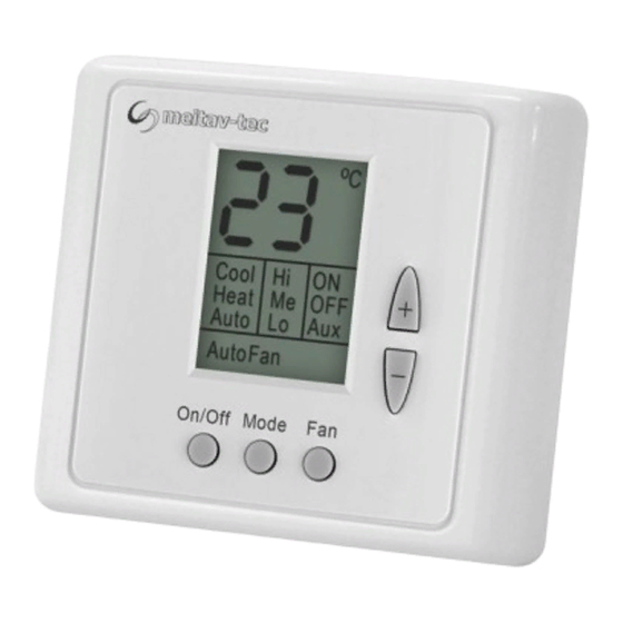
ETN24-P-3S-HU
(Cool and Heat)
Owner's Manual - Installation
and Operating Instructions
ETN24-P-3S-HU
(Cool and Heat)
Owner's Manual - Installation
and Operating Instructions
Meitav-tec Ltd (Contel group)
Tel: +972-3-9626462 Fax: +972-3-9626620
www.meitavtec.com - support@meitavtec.com
Meitav-tec Ltd (Contel group)
Tel: +972-3-9626462 Fax: +972-3-9626620
www.meitavtec.com - support@meitavtec.com
Advertisement

Related Manuals for meitav-tec ETN24-P-3S-HU


Summary of Contents for meitav-tec ETN24-P-3S-HU
- Page 1 ETN24-P-3S-HU (Cool and Heat) Owner's Manual - Installation and Operating Instructions Meitav-tec Ltd (Contel group) Tel: +972-3-9626462 Fax: +972-3-9626620 www.meitavtec.com - support@meitavtec.com ETN24-P-3S-HU (Cool and Heat) Owner's Manual - Installation and Operating Instructions Meitav-tec Ltd (Contel group) Tel: +972-3-9626462 Fax: +972-3-9626620...
-
Page 2: Table Of Contents
Please read this manual carefully before installation and use. Index Options & Accessories Installation Instructions Wiring Connections DIP switch Configuration External Sensor Connection Technician Settings Operating Manual Please read this manual carefully before installation and use. Index Options & Accessories Installation Instructions Wiring Connections DIP switch Configuration... -
Page 3: Options & Accessories
Humidity Duct Sensor (Purchase separately) • GHU/DUCT: Humidity duct sensor For details on where to purchase accessories, please contact Meitav-tec for you’re nearest location or visit our web site at www.meitavtec.com 1. Options and Accessories Remote sensor option: •... -
Page 4: Installation Instructions
2. Installation Instructions Separate the front panel from back panel by depressing the tongue located in the top of the unit. Pull the back panel out. Line the back panel up against the wall or flat surface. Install three screws as required. Make electrical connections as shown on enclosed electrical wiring diagram. -
Page 5: Wiring Connections
3. Wiring Connections 4. DIP switch Configuration DIP switch S1 (3 switches) – Internal / External sensor Internal sensor: S1.1 – On S1.2 – Off S1.3 – On External sensor: S1.1 – On S1.2 – On S1.3 – Off DIP switch S2 (4 switches) – Not in use Default position: S2.1 –... -
Page 6: External Sensor Connection
5. External sensor connection N.TC. Sensor; Temperature ~ Resistance Characteristics Temp °C 10.0 12.8 15.6 18.3 21.1 23.9 26.7 29.4 32.2 Temp ° F 115.8 100.9 88.1 77.1 67.7 59.6 52.5 46.4 41.2 36.6 Res. k - Disconnect power to the thermostat 24Vac. - Connect external sensor to terminals T - 0. -
Page 7: Technician Settings
6. Technician Settings Set differential for valve 2°C…10°C, proportional output range 0-10Vdc or 2-10Vdc, ambient humidity (RH) indication, set point for humidity (set RH) and differential for proportional output 4%-20% RH. Note: If no key is pressed for 5 seconds – the thermostat will automatically return to normal display mode. - Page 8 On/Off Mode...
Need help?
Do you have a question about the ETN24-P-3S-HU and is the answer not in the manual?
Questions and answers