Table of Contents
Advertisement
Quick Links
LM5072 12Vout 25W PoE PD
Power Eval-Board for IP
Camera
1.0 Design Specifications
2.0 Design Description
This LM5072 25W PoE PD Power Eval-board is specially de-
signed for IP Net Cameras powered by PoE. As the PD side's
power converter of a PoE system, this Eval-board converts
48Vdc to 12Vdc to directly power the motor driver for the IP
Net Camera's body rotation and zoom lens. Other regulators
such as LM26400 from National Semiconductor can be used
to convert the 12Vdc to 3.3Vdc, 2.5Vdc, 1.8Vdc and 1.2Vdc
to power the processor of an IP Net Camera as shown in fig-
ure 11. This board can provide total power up to 25W as
specified by the PoE Plus IEEE802.3at standard. In addition,
this Eval-board can be interfaced to any PSE that follows de-
tection and classification procedures defined by the
IEEE802.3af standard. In summary, this Eval-board is the
ideal solution for a Pre-PoE Plus IP Net Camera application.
This design has 2 auxilliary inputs to allow use of inexpensive
12Vdc and 24Vac regulated adapters to take advantage of
the LM5072's versatile auxiliary power options. 12Vdc power
can by provided to the load, bypassing the LM5072, by con-
necting a 12Vdc regulated adapter to the 12V AUX Input Port.
When regulated 12Vdc is available, it can be delivered directly
to the load, bypassing the LM5072, by connecting to the 12V
AUX Input Port. When the regulated 12Vdc is present at the
12V AUX input port before 48V PoE voltage is present, the
PoE startup signature detection resistance of the PD is sig-
nificantly reduced. This signals the PSE to not deliver power
to the PD. If 12Vdc is added after 48V PoE voltage is present,
the PD signature resistance changes and will signal the PSE
to stop providing power to the PD. In either case the regulated
12Vdc will turn off the LM5072 and can reduce power losses
from the converter and the PoE line.
The LM5072's RAUX configuration is utilized for the 24V AUX
input port to bypass the internal hot swap MOSFET allowing
the 800mA current limit of the LM5072 to be ignored. This
allows the input voltage for the 24V AUX input port to go down
to 16Vdc and up to 60Vdc. A key function for automatic se-
lection of supply Dominance Option is implemented for the
© 2008 National Semiconductor Corporation
Inputs
Output #1
VinMin=38V
Vout1=12V
VinMax=60V
Iout1=2.1A
National Semiconductor
LM5072
Honsun Tan
February 2008
24V AUX input port. By connecting pin 1 and pin 2 by a
jumper, as shown in figure 4, the 24V AUX is made to be the
dominant input voltage, even if 48V PoE input voltage is
present. Alternatively, if pin 2 and pin 3 are jumpered, as
shown in figure 4, the LM5072 will be placed in non-domi-
nance mode.
The theory and general application of PoE is beyond the
scope of this document. For detailed PoE information, please
see the LM5072 datasheet.
This document includes a schematic, BOM, layout and de-
tailed test results.
3.0 Features
Energy Efficient Eval-Board
DC/DC converter efficiency of 89% at PoE 48Vin with 25W
Load.
Overall efficiency of 85.5% at PoE 48Vin with 25W load.
DC/DC converter efficiency of 90% at 24Vin with 25W load.
Overall efficiency of 89% at 24Vin with 25W load.
Versatile Input Power Options
PoE input Port: 38Vdc-60Vdc range with PoE interface.
24V AUX input Port: 24Vac from inexpensive 24Vac adapter
or 16Vdc-60Vdc range
12V AUX input Port: Regulated 12Vdc from inexpensive
12Vdc adapter.
Full Protection for PoE
Compliant 802.3af PD interface
Inrush current limit.
Accurate 800mA over current protection.
Short-circuit protection, hiccup mode.
Input UVLP with 7V hysteresis, 37V on and 30V shutdown
LED indicates power from PoE
Uses Standard Transformer FA2900 from Coilcraft
This Eval-board is easily modified to 3.3Vdc, 5Vdc, 9Vdc and
15Vdc output with standard Coilcraft transformers FA2677,
FA2898, FA2899 and FA2901 respectively.
www.national.com
Advertisement
Table of Contents

Related Manuals for National Semiconductor LM5072


Summary of Contents for National Semiconductor LM5072
-
Page 1: Design Specifications
Alternatively, if pin 2 and pin 3 are jumpered, as power converter of a PoE system, this Eval-board converts shown in figure 4, the LM5072 will be placed in non-domi- 48Vdc to 12Vdc to directly power the motor driver for the IP nance mode. - Page 2 4.0 Schematic www.national.com...
-
Page 3: Bill Of Materials
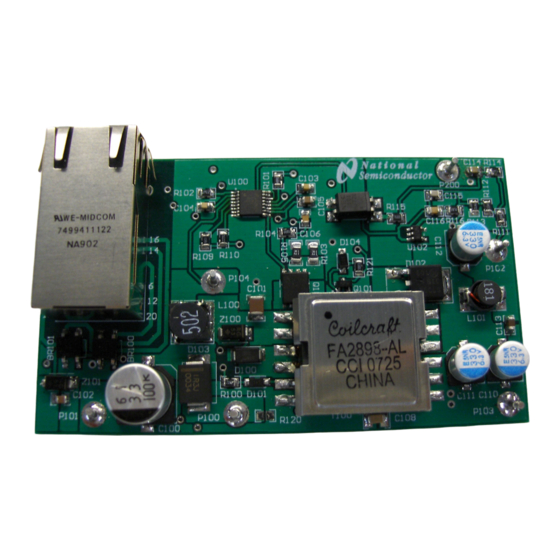
5.0 Bill of Materials FIGURE 2. BOM www.national.com... - Page 4 6.0 Other Operating Values Operating Values Description Parameter Value Unit Modulation Frequency Frequency Total output power Pout Steady State Efficiency Efficiency Control scheme Control scheme current Mode Peak-to-peak ripple voltage Vout p-p Static load regulation Static load Dynamic load regulation Dynamic load 7.0 Board Photos boardphoto1...
- Page 5 layout FIGURE 4. PCB Board Outline layout1 FIGURE 5. Layout Drawing 9.0 Waveforms www.national.com...
- Page 6 waveform FIGURE 6. DC to DC Converter Efficiency at PoE Input www.national.com...
- Page 7 www.national.com waveform1...
- Page 8 waveform2 FIGURE 8. DC to DC Converter Efficiency at 24V AUX Input www.national.com...
- Page 9 waveform3 FIGURE 9. Overall Efficiency at 24V AUX Input www.national.com...
- Page 10 waveform4 FIGURE 10. Ripple and Noise www.national.com...
-
Page 11: Physical Dimensions
10.0 Physical Dimensions inches (millimeters) unless otherwise noted 11.0 Appendix diagram FIGURE 11. Power Block Diagram for IP Camera www.national.com... -
Page 12: Life Support Policy
Notes National Semiconductor's design tools attempt to recreate the performance of a substantially equivalent physical implementation of the design. Reference designs are created using National's published specifications as well as the published specifications of other device manufacturers. While National does update this information periodically, this information may not be current at the time the reference design is built. - Page 13 STANDARD TERMS AND CONDITIONS FOR EVALUATION MODULES Delivery: TI delivers TI evaluation boards, kits, or modules, including any accompanying demonstration software, components, or documentation (collectively, an “EVM” or “EVMs”) to the User (“User”) in accordance with the terms and conditions set forth herein. Acceptance of the EVM is expressly subject to the following terms and conditions.
- Page 14 FCC Interference Statement for Class B EVM devices NOTE: This equipment has been tested and found to comply with the limits for a Class B digital device, pursuant to part 15 of the FCC Rules. These limits are designed to provide reasonable protection against harmful interference in a residential installation.
- Page 15 【無線電波を送信する製品の開発キットをお使いになる際の注意事項】 開発キットの中には技術基準適合証明を受けて いないものがあります。 技術適合証明を受けていないもののご使用に際しては、電波法遵守のため、以下のいずれかの 措置を取っていただく必要がありますのでご注意ください。 1. 電波法施行規則第6条第1項第1号に基づく平成18年3月28日総務省告示第173号で定められた電波暗室等の試験設備でご使用 いただく。 2. 実験局の免許を取得後ご使用いただく。 3. 技術基準適合証明を取得後ご使用いただく。 なお、本製品は、上記の「ご使用にあたっての注意」を譲渡先、移転先に通知しない限り、譲渡、移転できないものとします。 上記を遵守頂けない場合は、電波法の罰則が適用される可能性があることをご留意ください。 日本テキサス・イ ンスツルメンツ株式会社 東京都新宿区西新宿6丁目24番1号 西新宿三井ビル 3.3.3 Notice for EVMs for Power Line Communication: Please see http://www.tij.co.jp/lsds/ti_ja/general/eStore/notice_02.page 電力線搬送波通信についての開発キットをお使いになる際の注意事項については、次のところをご覧くださ い。http://www.tij.co.jp/lsds/ti_ja/general/eStore/notice_02.page SPACER EVM Use Restrictions and Warnings: 4.1 EVMS ARE NOT FOR USE IN FUNCTIONAL SAFETY AND/OR SAFETY CRITICAL EVALUATIONS, INCLUDING BUT NOT LIMITED TO EVALUATIONS OF LIFE SUPPORT APPLICATIONS.
- Page 16 SPACER Disclaimers: 6.1 EXCEPT AS SET FORTH ABOVE, EVMS AND ANY WRITTEN DESIGN MATERIALS PROVIDED WITH THE EVM (AND THE DESIGN OF THE EVM ITSELF) ARE PROVIDED "AS IS" AND "WITH ALL FAULTS." TI DISCLAIMS ALL OTHER WARRANTIES, EXPRESS OR IMPLIED, REGARDING SUCH ITEMS, INCLUDING BUT NOT LIMITED TO ANY IMPLIED WARRANTIES OF MERCHANTABILITY OR FITNESS FOR A PARTICULAR PURPOSE OR NON-INFRINGEMENT OF ANY THIRD PARTY PATENTS, COPYRIGHTS, TRADE SECRETS OR OTHER INTELLECTUAL PROPERTY RIGHTS.
-
Page 17: Important Notice
IMPORTANT NOTICE Texas Instruments Incorporated and its subsidiaries (TI) reserve the right to make corrections, enhancements, improvements and other changes to its semiconductor products and services per JESD46, latest issue, and to discontinue any product or service per JESD48, latest issue.
Need help?
Do you have a question about the LM5072 and is the answer not in the manual?
Questions and answers