
Subscribe to Our Youtube Channel
Related Manuals for National Semiconductor LM32


Summary of Contents for National Semiconductor LM32
- Page 1 National Semiconductor is now part of Texas Instruments. Search http://www.ti.com/ for the latest technical information and details on our current products and services. 1 of 22...
- Page 2 Revision B November 9, 2004 LM32, LM40, LM41 Evaluation Board User’s Guide © Copyright 2004 National Semiconductor Corporation www.national.com 2 of 22...
-
Page 3: Table Of Contents
LM32, LM40, LM41 Evaluation Board User’s Guide Table of Contents Table of Contents References 1.0 Introduction 1.1 Block Diagram 2.0 Quick Start 2.1 Quick Start Diagram 2.2 LM32 Quick Start 2.3 LM40 Quick Start 2.4 LM41 Quick Start 3.0 Functional Description 3.1 Evaluation Board Connection Tables... -
Page 4: Lm32, Lm40, Lm41 Evaluation Board User's Guide
“LM41 Hardware Monitor with Thermal Diode Inputs and SensorPath™ Bus” The latest copy of the LM32, LM40, LM41 datasheets can be obtained by going to the National Semiconductor website www.national.com, by searching on “LM32”, “LM40”, or “LM41”, and then downloading the appropriate datasheet file. -
Page 5: Introduction
(SWD), provides the address See Section 4.0 for software installation details. (ADD) select signal, and relays the information from the LM32, LM40, or LM41 to the PC via After the SensorEval software is running, the the USB lines. -
Page 6: Quick Start
1. Install the CD into the CD drive of the computer and install the SensorEval software (see Section 4.0). Hookup the USB cable between the PC or notebook computer and the LM32/LM40/LM41 Evaluation Board as shown in Quick Start Diagram below. -
Page 7: Lm32 Quick Start
The Screen should look like this: icon on the desktop. 2. The first screen will look like this: Select the LM32 Evaluation Board. Click OK. 3. The next screen will look like this: For Register 0A select Enable for Temp Sensor 0, 1 and 2.Note that Temp2 (Remote sensor... - Page 8 The user may then select whatever directory and file name of their choice and click on “Open”. Data will be stored in the file for each date/time and temperature. © Copyright 2004 National Semiconductor Corporation www.national.com 8 of 22...
-
Page 9: Lm40 Quick Start
Select Enabled for Register 0A Temp Sensor (above) displays the registers 00hex through (0,1,2) Enable. The temperature readings for 04hex. Temp0 (Local) Temp 1 (Q2) and Temp2 (Q1) will be displayed in Register 09 screens. © Copyright 2004 National Semiconductor Corporation www.national.com 9 of 22... - Page 10 “Open”. Data will be stored in the file for each The voltages that are present at the voltage date/time and temperature. inputs of the LM40 will be displayed in Register 11. © Copyright 2004 National Semiconductor Corporation www.national.com 10 of 22...
-
Page 11: Lm41 Quick Start
Select Enable for Register 0A Temp Sensor (above) displays the registers 00hex through (0,1) Enable. The temperature readings for 04hex. Temp0 (Local) and Temp1 (Q2) will be displayed in Register 09 screens. © Copyright 2004 National Semiconductor Corporation www.national.com 11 of 22... - Page 12 “Open”. Data will be stored in the file for each The voltages that are present at the voltage date/time and temperature. inputs of the LM41 will be displayed in Register © Copyright 2004 National Semiconductor Corporation www.national.com 12 of 22...
-
Page 13: Functional Description
It’s that simple! The user (ADD) select signal, and relays the information doesn’t have to provide any power or external from the LM32, LM40, or LM41 to the PC via signals to the evaluation board. the USB lines. -
Page 14: Lm40 Evaluation Board Connections Table
LM40. A jumper connects to the emitter (cathode) of Q1, a MMBT3904 transistor. These Headers are not used for evaluation board J4, J5 purposes. They are not stuffed or used. © Copyright 2004 National Semiconductor Corporation www.national.com 14 of 22... -
Page 15: Lm41 Evaluation Board Connections Table
These Headers are not used for evaluation board J4, J5 purposes. They are not stuffed or used. Jumper these pins so that the +3.3V can be connected to the +5VIN input to the LM41. © Copyright 2004 National Semiconductor Corporation www.national.com 15 of 22... -
Page 16: Software Installation And Operation
LM32/LM40/LM41 Evaluation Board using make the LM32, LM40, LM41 Evaluation Board operate SensorEval software: with the user’s PC. It is assumed that the user will be using a PC with a Pentium® III or higher processor and 1. Run the SensorEval program by either double- Microsoft Windows®... -
Page 17: Electrical And Mechanical Specifications
100 mA max. VDC for board power. * NO EXTERNAL POWER SUPPLY INPUTS ARE REQUIRED 5.2 Electrical Schematic Page 1 of 2 Pages of the Schematic of the LM32/LM40/LM41 Evaluation Board © Copyright 2004 National Semiconductor Corporation www.national.com 17 of 22... - Page 18 5.2 Electrical Schematic (continued) Page 2 of 2 Pages of the Schematic of the LM32/LM40/LM41 Evaluation Board © Copyright 2004 National Semiconductor Corporation www.national.com 18 of 22...
-
Page 19: Evaluation Board Layout
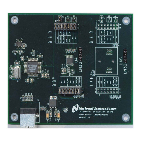
5.3 Evaluation Board Layout Figure 5.3 Layout diagram of the LM32/LM40/LM41 Evaluation Board © Copyright 2004 National Semiconductor Corporation www.national.com 19 of 22... -
Page 20: Bill Of Materials
IC, EEPROM, Atmel AT24C02-10SI-2.7 LM32, LM40, or LM41CIMF Device Under Test (DUT) U4(for socket) LM32, LM40, or LM41CIMF [Do Not Stuff] used with socket Socket, Loranger, 14-pin TSSOP-14 [Do Not Stuff] Crystal, 12 MHz, Pletronics 2S1200G140 Circuit Board, Fabricated, LM32, LM40, LM41 Evaluation Board, Rev. -
Page 21: Mechanical Specifications
#30 for 4-40 screw clearance fit (4 Places) 5.4.3 Electrostatic Discharge (ESD) Precautions The user shall use ESD precautions as specified in National Semiconductor ESD control document (SC)CSI-3-038 available through www.national.com. © Copyright 2004 National Semiconductor Corporation www.national.com 21 of 22... - Page 22 THE UNUSED PRODUCT FOR A REFUND OF THE PURCHASE PRICE PAID, IF ANY. The LM32, LM40, LM41 Evaluation Boards are intended for product evaluation purposes only and are not intended for resale to end consumers, are not authorized for such use and are not designed for compliance with European EMC Directive 89/336/EEC, or for compliance with any other electromagnetic compatibility requirements.
Need help?
Do you have a question about the LM32 and is the answer not in the manual?
Questions and answers