
Related Manuals for National Semiconductor LMX2531LQ1910E


Summary of Contents for National Semiconductor LMX2531LQ1910E
- Page 1 LMX2531LQ1910E Evaluation Board Operating Instructions National Semiconductor Corporation Wireless Communications, RF Products Group 2900 Semiconductor Dr. Santa Clara, CA, 95052-8090 LMX2531LQ1910EFPEB Rev 1.20.2006...
-
Page 2: Table Of Contents
L M X 2 5 3 1 L Q 1 9 1 0 E E V A L U A T I O N B O A R D O P E R A T I N G I N S T R U C T I O N S ABLE OF ONTENTS ........................ -
Page 3: General Description
CodeLoader software included can be run on a PC to facilitate the LMX2531LQ1910E internal register programming for the evaluation and measurement. In addition to this cable assembly, there is a microwire buffer board that ensures that the proper voltage levels are provided to the microwire inputs and also this reduces digital noise from computers through the parallel port. -
Page 4: Phase Noise
L M X 2 5 3 1 L Q 1 9 1 0 E E V A L U A T I O N B O A R D O P E R A T I N G I N S T R U C T I O N S Phase Noise... -
Page 5: Phase Noise With Narrow Loop Filter (Internal Divide By 2 Disabled)
L M X 2 5 3 1 L Q 1 9 1 0 E E V A L U A T I O N B O A R D O P E R A T I N G I N S T R U C T I O N S Phase Noise with Narrow Loop Filter (Internal Divide by 2 Disabled) The plots to the left show the true phase noise capability of the... -
Page 6: Phase Noise With Narrow Loop Filter (Internal Divide By 2 Enabled)
L M X 2 5 3 1 L Q 1 9 1 0 E E V A L U A T I O N B O A R D O P E R A T I N G I N S T R U C T I O N S Phase Noise with Narrow Loop Filter (Internal Divide by 2 Enabled) The plots to the left show the true phase noise capability of the... -
Page 7: Spurs (Internal Divide By 2 Disabled)
L M X 2 5 3 1 L Q 1 9 1 0 E E V A L U A T I O N B O A R D O P E R A T I N G I N S T R U C T I O N S Spurs (Internal Divide by 2 Disabled) Spur at 200 kHz offset at a worst case frequency of 1830.2 MHz is -90.2 dBc. -
Page 8: Spurs (Internal Divide By 2 Enabled)
L M X 2 5 3 1 L Q 1 9 1 0 E E V A L U A T I O N B O A R D O P E R A T I N G I N S T R U C T I O N S Spurs (Internal Divide by 2 Enabled) Spur at 200 kHz offset at a frequency of 915.1 MHz is –95.5 dBc. -
Page 9: Codeloader Settings
L M X 2 5 3 1 L Q 1 9 1 0 E E V A L U A T I O N B O A R D O P E R A T I N G I N S T R U C T I O N S CodeLoader Settings For the CodeLoader program, the default reference oscillator used for these instructions was 10 MHz, but there is a mode for a 61.44 MHz oscillator as well. - Page 10 L M X 2 5 3 1 L Q 1 9 1 0 E E V A L U A T I O N B O A R D O P E R A T I N G I N S T R U C T I O N S CodeLoader is set up to load the registers and initialize the part in the correct way.
-
Page 11: Schematic
L M X 2 5 3 1 L Q 1 9 1 0 E E V A L U A T I O N B O A R D O P E R A T I N G I N S T R U C T I O N S Schematic POWER VccVCO... -
Page 12: Bill Of Materials
Header POWER FCI Electronics 52601-S10-8 Metal/Plastic Header uWire Johnson Components 142-0701-851 Metal Fout, OSCin, Vcc PCB Board National Semiconductor LMX2531LQEBPCB 62 mil Thick 1st Layer 10 mils National Semiconductor LMX2531 LLP36 Silicon LMX2531 Place Across: Com Con Connectors CCIJ255G 2-Pin... -
Page 13: Top Layer
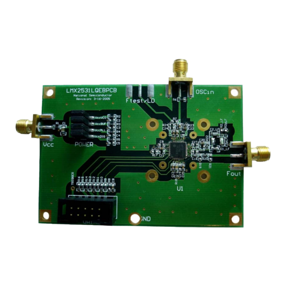
L M X 2 5 3 1 L Q 1 9 1 0 E E V A L U A T I O N B O A R D O P E R A T I N G I N S T R U C T I O N S Top Layer... -
Page 14: Mid Layer 1 "Ground Plane
L M X 2 5 3 1 L Q 1 9 1 0 E E V A L U A T I O N B O A R D O P E R A T I N G I N S T R U C T I O N S Mid Layer 1 "Ground Plane"... -
Page 15: Mid Layer 2 "Power
L M X 2 5 3 1 L Q 1 9 1 0 E E V A L U A T I O N B O A R D O P E R A T I N G I N S T R U C T I O N S Mid Layer 2 "Power"... -
Page 16: Bottom Layer "Signal
L M X 2 5 3 1 L Q 1 9 1 0 E E V A L U A T I O N B O A R D O P E R A T I N G I N S T R U C T I O N S Bottom Layer "Signal"... -
Page 17: Top Build Diagram
L M X 2 5 3 1 L Q 1 9 1 0 E E V A L U A T I O N B O A R D O P E R A T I N G I N S T R U C T I O N S Top Build Diagram... - Page 18 EVALUATION BOARD/KIT/MODULE (EVM) ADDITIONAL TERMS Texas Instruments (TI) provides the enclosed Evaluation Board/Kit/Module (EVM) under the following conditions: The user assumes all responsibility and liability for proper and safe handling of the goods. Further, the user indemnifies TI from all claims arising from the handling or use of the goods.
- Page 19 FCC Interference Statement for Class B EVM devices This equipment has been tested and found to comply with the limits for a Class B digital device, pursuant to part 15 of the FCC Rules. These limits are designed to provide reasonable protection against harmful interference in a residential installation. This equipment generates, uses and can radiate radio frequency energy and, if not installed and used in accordance with the instructions, may cause harmful interference to radio communications.
- Page 20 【 【 Important Notice for Users of this Product in Japan】 】 This development kit is NOT certified as Confirming to Technical Regulations of Radio Law of Japan If you use this product in Japan, you are required by Radio Law of Japan to follow the instructions below with respect to this product: 1.
- Page 21 EVALUATION BOARD/KIT/MODULE (EVM) WARNINGS, RESTRICTIONS AND DISCLAIMERS For Feasibility Evaluation Only, in Laboratory/Development Environments. Unless otherwise indicated, this EVM is not a finished electrical equipment and not intended for consumer use. It is intended solely for use for preliminary feasibility evaluation in laboratory/development environments by technically qualified electronics experts who are familiar with the dangers and application risks associated with handling electrical mechanical components, systems and subsystems.
- Page 22 IMPORTANT NOTICE Texas Instruments Incorporated and its subsidiaries (TI) reserve the right to make corrections, enhancements, improvements and other changes to its semiconductor products and services per JESD46, latest issue, and to discontinue any product or service per JESD48, latest issue.
Need help?
Do you have a question about the LMX2531LQ1910E and is the answer not in the manual?
Questions and answers