Advertisement
Quick Links
WARNING: Improper installation, adjustment,
alteration, service or maintenance can cause
property damage, injury or death. Read the installation,
operating and maintenance instructions thoroughly
before installing or servicing this equipment.
INSTALLATION / OPERATION / MAINTENANCE
Applies to:
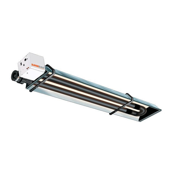
Gas-Fired, Tubular, Radiant,
Low-Intensity Infrared Heater
Model VSUS & VSLUS
120V 60Hz
OWNERS MANUAL
OWNERS MANUAL
Part # 700110
Advertisement

Related Manuals for Ambirad VSUS


Summary of Contents for Ambirad VSUS
- Page 1 INSTALLATION / OPERATION / MAINTENANCE Model VSUS & VSLUS Applies to: 120V 60Hz Gas-Fired, Tubular, Radiant, Low-Intensity Infrared Heater OWNERS MANUAL OWNERS MANUAL WARNING: Improper installation, adjustment, alteration, service or maintenance can cause property damage, injury or death. Read the installation, operating and maintenance instructions thoroughly before installing or servicing this equipment.
- Page 2 Introduction. Welcome to the new range of vacuum infra-red and attention is required to ensure that working heaters. Local regulations may vary and it is the at height regulations are adhered to. installer’s responsibility to ensure that such regulations are satisfied. PLEASE READ this document prior to All installation, assembly, commissioning and installation to familiarize yourself with the...
-
Page 3: Installation Requirements
1. Installation Requirements. 1.2 Heater Suspension Health and Safety Attachment to the heater support lugs should be Heaters intended heating made by a D shackle. The hanging attachments non-residential indoor spaces and should overhead steelwork etc. must be purpose only be installed where flammable gases made to good sound engineering practice or of or vapors are not generally present. - Page 4 Figure 1. Recommended Methods of Heater Suspension.
- Page 5 Clearance to Combustibles. Minimum clearance to combustibles are shown in Figures 2a/2b. Use in conjunction with Table 1 below. IMPORTANT: The stated clearance to combustibles represents a surface temperature of 90°F (50°C) above room temperature. Building material with a low heat tolerance (such as plastics, vinyl siding, canvas, tri-ply, etc.) may be subject to degradation at lower temperatures.
- Page 6 Figure 2a Clearance to Combustibles (U-Tube Variants). The minimum clearances to combustible materials are given in the tables below. These minimum distances MUST be adhered to at all times. Adequate clearance MUST be provided around air openings into the combustion chamber and there MUST be suitable clearance for accessibility and for combustion / ventilating air supplies.
- Page 7 Figure 2b Clearance to Combustibles (Linear Tube Variants). The minimum clearances to combustible materials are given in the tables below. These minimum distances MUST be adhered to at all times. Adequate clearance MUST be provided around air openings into the combustion chamber and there MUST be suitable clearance for accessibility and for combustion / ventilating air supplies.
- Page 8 Figure 3. Correct orientation of Ball Valve Gas Connection and Supply WARNING: Before installation, check that the local distribution conditions, nature of gas and pressure, and adjustment of the appliance are compatible. Gas Flow The gas connection to the heater is ½” N.P.T internal thread.
- Page 9 Table 3 Gas Supply Pressures Natural Gas LP/Propane Gas Gas Type 11.0 Required Gas Pressure (in W.C) 60,000 to 150,000 btu 11.0 Required Gas Pressure (in W.C) 170,000 to 200,000 btu 14.0 14.0 Max Supply Pressure (in W.C) Connection ½” N.P.T thread Gas Supply Electrical Connections The electrical supply to the heater is by three...
- Page 10 Figure 5c. Single and Multiple Heater Installations 120V Control KEY: G-GREEN 120V 60Hz 1 Ph W-WHITE Supply circuit BK-BLACK L1 (HOT) 110V Thermostat 120V Thermostat Burner 1 other burners Figure 5d. Single Heater Installations 24V Control METHOD:- Cut and strip pink cables linking terminals W1 and R KEY: Attach thermostat wires using suitable wire nuts.
- Page 11 Figure 5d. Internal burner wiring diagram 120V AC Fan 120V/60Hz AC Supply KEY: BL - BLUE BK - BLACK BR - BROWN GR - GREY G - GREEN K - PINK R - RED W - WHITE Y - YELLOW 120v/24VAC 60Hz Power ON (red) Pressure Switch...
- Page 12 degradation by the vent gases. 1.7 Ventilation Requirements Vent joints should be sealed and secured according vent manufacturers 1.7.1 Unvented units instructions. Should condensation occur the vent should be shortened or insulated. Heaters may be installed without a vent providing the governing building codes are met The terminal should be at least 3ft (0.91m) away and consideration is given to possibilities of from any air intake to the building.
- Page 13 Figure 6.a Vertical Venting. CODE APPROVED VENT THROUGH ROOF ROOF SEAL ALUMINUM 4" (101mm) O.D. OR 6" (152mm) O.D. FLUE 12'-0" (3.66m) 12'-0" (3.66m) (APPROXIMATE SEAL JOINTS WITH MAXIMUM DIMENSIONS) HIGH TEMPERATURE SILICONE 4" (101mm) TO 6" (152mm) DIA. ALUMINUM ADAPTER END OF RADIANT TUBE REQUIRED ONLY FOR 6"...
- Page 14 Technical Details No of Injectors ½” N.P.T nipple. Gas Connection 120 volt 1 phase 60Hz Electrical Supply 4” or 6” Vent size (in) 120 volt 1 phase 60Hz Unitary Fan Motor Details 1.2A MAX Current Rating Electronic Program Start up with Spark Ignition Ignition Min.
- Page 15 Natural Gas 0– 2000 ft (0-610m) Natural Gas 0– 2000 ft (0-610m) Natural Gas 2001- 4000 ft (611-1220m) Natural Gas 2001- 4000 ft (611-1220m) Size Size Size Size 80 100 125 150 80 100 125 150 3.5 3.0 2.6 3.5 3.0 2.6 “WC “WC “WC...
- Page 16 Table 7a: U-Tube Heater Tube Materials Combustion tube Radiant tube Model number BTU/Hr length (ft) length (ft) 45,720 40U20 10 (1-CC) 10 (1-MS) 60,000 60U20 42,720 40U30 10 (1-MS) 60,000 10 (1-CC) 60U30 10 (2#5’-MS) 80,000 80U30 100,000 100U35 10 (1-MS) 125,000 10 (1-AS) 125U35...
- Page 17 Table 7b: Linear Heater Tube Materials Tube Combustion tube Radiant tube Min distance to Model number BTU/Hr diameter length (ft) length (ft) bend (ft) 45,720 40S20 10’ (1-CC) 10’ (1-MS) 10’ 60,000 60S20 45,720 40S25 10’ 10’ (1-MS) 60,000 10’ (1-CC) 60S25 10’...
-
Page 18: Assembly Instructions
2. Assembly Instructions. PLEASE READ this section prior to Please ensure that all packaging is assembly to familiarize yourself with the disposed of in a safe environmentally components and tools you require at the friendly way. various stages of assembly. Carefully open the packaging and check the contents against the For your own safety we recommend the parts and check list. - Page 19 2.2.3.1 U-Tube Heaters Type ‘B3’ is a sliding reflector suspension Type ‘A2’ is a fixed reflector suspension bracket, tabbed with reflector fixing points. bracket and NOT fastened to the reflector. An oversized extra long ‘floating U bolt’ with An extra long ‘floating U bolt’...
- Page 20 2.2.3.3 Linear 3” SL Tube Heaters 2.2.3.4 Linear - 4” SL Tube Heaters Type ‘A1’ is a fixed reflector suspension Type ‘A’ is a fixed reflector suspension bracket, tabbed with reflector fixing points. bracket, tabbed with reflector fixing points. An oversized ‘U’...
- Page 21 Draw Band Coupling DRAW BAND COUPLING 2.2.4 Couplers BOLTS Bolts SELF TAPPING ZIP Self Tapping Zip There are two types of 3” and 4” couplers for SCREWS Screws joining radiant tubes, bends or optional bend kits as detailed in Table 8 opposite. Stainless A high temperature stainless steel coupling.
- Page 22 Secure overlapped reflectors onto all type ‘A’ brackets using nuts, bolts and flat mud 2.2.7 Bend(s) (where fitted) washers. The heater can be installed with 1 or 2 90° All other suspension brackets along the tube bends, or a 180° U bend. are type ‘B’...
- Page 23 2.2.8 End Caps. ensuring it is fully engaged. Secure with set pins. On U-Tube models only, position the end cap with no tube holes beneath the reflector profile 2.2.10 Fan Assembly. at the U bend end with the end cap flanges facing inwards.
- Page 24 Table 9. Possible Heater Orientations Bends must be fitted at a distance of at least 50% of the total heat exchanger length from the burner, e.g. for a 60ft long heater, the closest to the burner a bend can be is 30ft.
- Page 25 Figure 10. Heater Assembly: Model U tube 40U20 and 60U20. 19¼"...
- Page 26 Figure 11. Heater Assembly: Model U tube 40U30, 60U30 and 80U30. 19¼"...
- Page 27 Figure 12. Heater Assembly: Model U tube 60U40 and 80U40 19¼"...
- Page 28 Figure 13. Heater Assembly: Model U tube 100U35, 125U35 and 150U35 26¼"...
- Page 29 Figure 14. Heater Assembly: Model U tube 125U45, 150U45 and 170U45 26¼"...
- Page 30 Figure 15. Heater Assembly: Model U tube 170U55 and 200U55 26¼"...
- Page 31 Figure 16. Heater Assembly: Model U tube 170U65 and 200U65 26¼"...
- Page 32 Figure 17. Heater Assembly: Model U tube 200U75 26¼"...
- Page 33 Figure 18. Heater Assembly: Model Linear 40S20 and 60S20.
- Page 34 Figure 19. Heater Assembly: Model Linear 40-S25, 60-S25 and 80-S25.
- Page 35 Figure 20. Heater Assembly: Model Linear 40S30, 60S30 and 80S30.
- Page 36 Figure 21. Heater Assembly: Model Linear 60-S40 and 80-S40.
- Page 37 Figure 22. Heater Assembly: Model Linear 100S30.
- Page 38 Figure 23. Heater Assembly: Model Linear 100S40, 125S40 and 150S40...
- Page 39 Figure 24. Heater Assembly: Model Linear 100S50, 125S50, 150S50, 170S50 and 200S50...
- Page 40 Figure 25. Heater Assembly: Model Linear 125S60, 150S60, 170S60 and 200S60...
- Page 41 Figure 26. Heater Assembly: Model Linear 170S70 and 200S70...
- Page 42 Figure 27. Heater Assembly: Model Linear 200S80...
-
Page 43: Start Up Instructions
3. Start Up Instructions. These appliances should be commissioned by a qualified mechanical contractor. Tools Required. The following tools and equipment are advisable Suitable alternative tools may be used. to complete the tasks laid out in this manual. Large Adjustable Small Flat Leather Phillips... - Page 44 illuminated and fan running, but the ‘burner on’ heater proceeds to ignite in the normal way. lamp being off. Close the controls door and secure with the Check the operation of the pressure proving screw. switch as follows: With the heater running normally, pull off the silicone rubber tube connecting the vacuum switch to the combustion chamber.
-
Page 45: Servicing Instructions
4. Servicing Instructions. These appliances should be serviced annually by a competent person to ensure safe and efficient operation. In exceptional dusty or polluted conditions more frequent servicing may be required. Servicing work should be carried out by a qualified mechanical contractor. - Page 46 4.3 Burner Removal 4.4 Burner Gas Injector Servicing Step 1: Isolate power and gas supplies. Step 1.a: Remove the burner support casting and gasket. Step 2: Unplug the power connectors. Step 1.b: The burner head assembly can be Step 3: Detach the gas supply as shown disconnected by separating the connectors of below, taking care to support the burner the ignition lead assembly and removing the...
- Page 47 Step 5: Refit the electrode assembly and ensure 4.5 Burner Head and Electrode Servicing the connections are secure to prevent incorrect Step 1: Check the pepper pot burner head for sparking of the spark electrode. contamination. If necessary this can be removed.
- Page 48 Step 4: Withdraw the turbulators from the Step 4: Remove the fan orifice plate spinning. appliance. Carefully note their condition and position. Replace turbulators if necessary. Step 5: Inspect the impeller and remove any dust with a soft brush. Step 5: The turbulators should be cleaned with a soft brush.
-
Page 49: Spare Parts
5. Spare Parts. Required Spares Note: Any spare part components that are In order to aid troubleshooting and servicing we not approved by the manufacturer could recommend that the components shown in this invalidate the approval of the appliance and the section should be stocked. -
Page 50: Troubleshooting Guide
6. Troubleshooting Guide. START Ensure gas & electricity supplies are enabled. Turn any external timer to call for heat (if fitted). CHECK: - Does the Power On Is there power to the 1. Transformer light illuminate? burner? 2. Integrity of wiring connections. 3. - Page 51 6. Troubleshooting Guide. To aid the troubleshooting process, the UT controller has a LED flash code diagnostic sequence: Steady Off No control power Steady On Power applied, control OK Combustion pressure switch open with blower on 1 Flash Combustion pressure switch closed with blower off 2 Flashes Lockout from the three ignition trials 3 Flashes...
-
Page 52: Replacing Parts
7. Replacing Parts. 7.2 Air Pressure Switch Replacement Turn off gas and any electrical supplies to the heater before starting repair work. Step 1: Open left hand door. Disconnect the two silicone impulse tubes from the pressure switch. 7.1 Burner Controller Replacement Step 1: Loosen screw in burner lid and open the right hand burner access door. - Page 53 Step 6: Detach the two screws holding the front 7.3 Gas Valve Replacement of the gas valve. Step 1: Remove the burner assembly as described in section 4 (Servicing). Step 2: Open the right hand access door and disconnect the burner controller from the wiring harness.
-
Page 54: Optional Extra Kits
8. Optional Extra Kits. Natural Gas Aluminized Stainless Steel 180° Altitude Combustion 90° Elbow Steel End Cap End Cap U-Bend Conversion Kit Air inlet Kit Kit (1 Off) Kit (1Pair) Kit (1 Pair) MODEL UT & SL 4” SL ONLY 202255 3184-1- 3185-1-... - Page 57 9. User & Operating Instructions. AmbiRad is the manufacturer of a series of tubular infra-red heaters designed for overhead heating of industrial and commercial buildings. Individual heating units are suspended from the roof or mounted at an angle on the wall.
Need help?
Do you have a question about the VSUS and is the answer not in the manual?
Questions and answers