Table of Contents
Advertisement
Quick Links
INSTALLATION / OPERATION / MAINTENANCE
Model VCLUS/VCLUS HL 120V 60Hz
Applies to:
WARNING: Improper installation, adjustment,
alteration, service or maintenance can cause
property damage, injury or death. Read the installation,
operating and maintenance instructions thoroughly
before installing or servicing this equipment.
700111
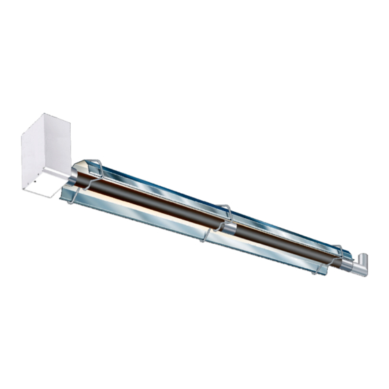
Gas-Fired, Tubular, Radiant,
Low-Intensity Infrared Heater
Vision Range
VCLUS / VCLUS HL OWNERS MANUAL
Advertisement
Table of Contents

Related Manuals for Ambirad VCLUS 40-S10


Summary of Contents for Ambirad VCLUS 40-S10
- Page 1 INSTALLATION / OPERATION / MAINTENANCE Model VCLUS/VCLUS HL 120V 60Hz Applies to: Gas-Fired, Tubular, Radiant, Low-Intensity Infrared Heater Vision Range VCLUS / VCLUS HL OWNERS MANUAL WARNING: Improper installation, adjustment, alteration, service or maintenance can cause property damage, injury or death. Read the installation, operating and maintenance instructions thoroughly before installing or servicing this equipment.
-
Page 2: Installation Requirements
Introduction. Welcome to the new range of powered harsh and servicing is undertaken on radiant tube environment infrared heaters. Local regulations heaters specified in these instructions, due care may vary and it is the installer’s responsibility to and attention is required to ensure that working ensure that such regulations are satisfied. - Page 3 Installation Code, CSA B149.1, and are so to carry the whole weight of the heater. In the marked. event suitable roof steelwork being unavailable, additional steelwork should be fitted Ensure that minimum clearances will be to enable vertical hangers to be used for maintained to vehicles parked below the suspending the heaters.
- Page 4 ON U TUBE VARIANTS THE HEATER SHOULD SLOPE DOWNWARDS TOWARDS THE RETURN BEND AND ON LINEAR VARIANTS SHOULD SLOPE DOWNWARDS TOWARDS BURNER BY APPROX. ½” FOR HORIZONTAL INSTALLATIONS AS SHOWN BELOW (DIAGRAMS EXAGGERATED FOR CLARITY) 1/2” 1/2” Outlet U bend Linear heater side view U Tube heater side view Clearance to Combustibles.
- Page 5 Figure 2 Clearance to Combustibles (Standard indoor reflectors). The minimum clearances to combustible materials are given in the tables below. These minimum distances MUST be adhered to at all times. Adequate clearance MUST be provided around air openings into the combustion chamber and there MUST be suitable clearance for accessibility and for combustion / ventilating air supplies.
- Page 6 Gas Connection and Supply Figure 3. Correct orientation of Ball Valve WARNING: Before installation, check that the local distribution conditions, nature of gas and pressure, and adjustment of the appliance are compatible. Gas Flow The gas connection on the heater is ½” N.P.T Gas Flow internal thread.
- Page 7 CONNECTOR MUST BE INSTALLED IN A “U” CONFIGURATION. FOR HEATERS UPTO 150,000 BTU/H, A 24” LONG CONNECTOR OF AT LEAST ½” ID MUST BE USED. FOR HEATERS ABOVE 150,000 BTU/H, A 36” LONG CONNECTOR OF AT LEAST ¾” NOMINAL ID MUST BE USED. Table 4 Gas Supply Pressures Natural Gas LP/Propane Gas...
-
Page 8: Supply Circuit
Figure 5b. Single and Multiple Heater Installations 120V Control (VCLUS) 120V 60Hz 1 Ph Supply circuit L1 (HOT) 120V Thermostat 110V Thermostat Burner 1 Other burners KEY: G-GREEN other burners W-WHITE BK-BLACK Burner If heaters are wired using the method shown above, a link wire must be fitted to the burner terminals as shown in the diagram opposite. - Page 9 Figure 6. Internal Burner Wiring Diagram. (VCLUS) O p tio n al 24V sin gle stage T h erm os tat 24V S tat 120V A C Fan 120V A C T erm in als T erm in als S up ply K E Y : B L - B LU E B K - B LA C K...
- Page 10 Figure 7b. Internal Burner Wiring Diagram. (VCLUS HL) 24V Tw o stage Therm ostat 24V A C S tat 120V A C Fan 120V A C K EY : Term inals Term inals S upply B L - BLU E B K - B LA C K B R - B R O W N G R - G R E Y...
- Page 11 Standard vent terminals must extend at least 1.6 Vent Requirements and Details 6” (152mm) from the wall and at least 24” (609mm) from any combustible overhang. 1.6.1 Unvented units Protect the building material from degradation Heaters may be installed without a vent by the vent gases.
-
Page 12: Plan View
Figure 8.a Vertical Venting. CODE APPROVED VENT THROUGH ROOF ROOF SEAL APPROVED CAT III VENT PIPE ALUMINUM 4" (101mm) O.D. OR 6" (152mm) O.D. FLUE 12'-0" (3.66m) 12'-0" (3.66m) SEAL JOINTS WITH (APPROXIMATE HIGH TEMPERATURE SILICONE MAXIMUM DIMENSIONS) 4" (101mm) TO 6" (152mm) DIA. ALUMINUM ADAPTER CAT III ADAPTER REQUIRED ONLY FOR 6"... - Page 13 Technical Details - Table 5a (VCLUS) No of Injectors ½” N.P.T Gas Connection 120 volt 1 phase 60Hz Electrical Supply 4” or 6” (101mm or 152mm) Vent size (in) 120 volt 1 phase 60Hz Unitary Fan Motor Details 1.2A MAX Current Rating Electronic Program Start up with Spark Ignition Ignition...
- Page 14 Technical Details continued USA & CANADA Natural Gas 0- 2000 ft (0-610m) MODEL Burner Orifice Plate 201063-57 201063-45 201063-29 201063-23 201063-26 201063-25 201063-24 201063-24 Part No. 201957 202132 Fan Type Fan Orifice 201970 L200281 201654 L200281 L200262 201637 201425 201911 Part No.
- Page 15 Technical Details - Table 5b (VCLUS HL) No of Injectors ½” N.P.T Gas Connection 120 volt 1 phase 60Hz Electrical Supply 4” or 6” (101mm or 152mm) Vent size (in) 120 volt 1 phase 60Hz Unitary Fan Motor Details 1.2A MAX Current Rating Electronic Program Start up with Spark Ignition Ignition...
- Page 16 Technical Details continued USA & CANADA Natural Gas 0- 2000 ft (0-610m) MODEL Burner Orifice Plate 201063-57 201063-77 201063-67 201063-23 201063-26 201063-25 201063-24 201063-24 Part No. 201957 202132 Fan Type Fan Orifice 202483 202479 L200301 L200281 L200262 201425 202133 201911 Part No.
-
Page 17: Straight Tube
Technical Details continued U TUBE STRAIGHT TUBE MODEL ● ● ● ● ● ● ● ● ● ● ● ● ● ● ● ● ● ● ● ● ● ● ● ● ● ● ● ● ● ● ● 200* TUBE TYPE MATERIAL MIN DISTANCE MODEL... -
Page 18: Assembly Instructions
2. Assembly Instructions. PLEASE READ this section prior to Please ensure that all packaging is assembly to familiarize yourself with the disposed of in a safe environmentally components and tools you require at the friendly way. various stages of assembly. Carefully open the packaging and check the contents against the For your own safety we recommend the parts and check list. - Page 19 Type ‘F’ are fixed reflector brackets. Slide the coupler over the tube ensuring that the screw stop has butted up to the tube ends. 2 x SCREWS TIGHTENED TO FIX REFLECTOR Using the Allen wrench to tighten the bolts. ...
- Page 20 2.2.5 Reflectors. 2.2.7 Bend(s) (where fitted) After removing the protective plastic coating (if The heater can be installed with 1 or 2 90° fitted), slip the reflectors through the hanger bends or a 180° U bend. brackets until they overlap each other. Slide the bend into the open end of the The first and second reflector are fixed at the coupler ensuring that the screw stop has butted...
- Page 21 2.2.8 Burner/Fan Assembly. Slide the burner assembly onto the open tube end, ensuring it is fully engaged. Secure with set screws. For the purpose of unvented applications, a 4” 90° elbow should be used on the terminating end of the radiant tube sections. This elbow should be turned with the outlet facing either side.
- Page 23 Figure 10. Heater Assembly: Model Linear VCLUS 40-S10 VCLUS HL 40-S10...
- Page 24 Figure 11. Heater Assembly: Model Linear VCLUS 40-S20, 60-S20, 80-S20. VCLUS HL 40-S20, 60-S20.
- Page 25 Figure 12. Heater Assembly: Model Linear VCLUS 40-S30, 60-S30, 80-S30, 100-S30.
- Page 26 Figure 13. Heater Assembly: Model Linear VCLUS 60-S40, 80-S40, 100-S40, 125-S40, 150-S40. VCLU HL 60-S40, 80-S40, 100-S40, 125-S40, 150-S40.
- Page 27 Figure 14. Heater Assembly: Model Linear VCLUS 100-S50, 125-S50, 150-S50, 170-S50, 200-S50. VCLUS HL 125-S50, 150-S50, 170-S50, 200-S50.
- Page 28 Figure 15. Heater Assembly: Model Linear VCLUS 125-S60, 150-S60, 170-S60, 200-S60. VCLUS HL 150-S60, 170-S60, 200-S60.
- Page 29 Figure 16. Heater Assembly: Model Linear VCLUS 150-S70, 170-S70, 200-S70. VCLUS HL 170-S70, 200-S70.
- Page 30 Figure 17. Heater Assembly: Model Linear VCLUS 170-S80 and 200-S80.
- Page 31 Figure 18. Heater Assembly: Model U tube VCLUS 40-U20, 60-U20, 80-U20. VCLUS HL 40-U20, 60-U20. 3' 3"...
- Page 32 Figure 19. Heater Assembly: Model U tube VCLUS 60-U40, 80-U40, 100-U40, 125-U40 and 150-U40. VCLUS HL 60-U40, 80-U40, 100-U40, 125-U40 and 150-U40. 3' 3"...
- Page 33 Figure 20. Heater Assembly: Model U tube VCLUS 125-U60, 150-U60, 170-U60 and 200-U60. VCLUS HL 150-U60, 170-U60, 200-U60. 3' 3"...
- Page 34 Figure 21. Heater Assembly: Model U tube VCLUS 170-U80 and 200-U80. 3' 3"...
-
Page 35: Start Up Instructions
3. Start Up Instructions. These appliances should be commissioned by a qualified mechanical contractor. Tools Required. The following tools and equipment are advisable Suitable alternative tools may be used. to complete the tasks laid out in this manual. Large Adjustable Small Flat Leather Phillips... - Page 36 counter-clockwise to decrease the pressure. Set the pressure to appropriate inches w.c. from the table of gas pressures and orifice plate dimensions for correct heater description. Switch off the power supply to the heating system. Disconnect ‘U’ tube manometer, then securely replace screw in pressure test nipple.
- Page 37 Commissioning chart Check installation has Ensure gas and electricity Disconnect gas hose from been carried out to these supplies are isolated. burner. instructions. Remove burner from tube and inspect burner head. (See servicing instructions). Reconnect gas hose. Open control housing and Replace burner on tube Open Manual valve.
-
Page 38: Servicing Instructions
4. Servicing Instructions. These appliances should be serviced annually by a competent person to ensure safe and efficient operation. In mildly dusty or polluted conditions more frequent servicing may be required. Servicing work should be carried out by a qualified mechanical contractor. Tools Required. - Page 39 removed from the radiant tube. 4.3 Burner Removal Step 1: Isolate power and gas supplies. Step 2: Disconnect the external power/control connections. Step 6: Remove the burner and position in a safe area to prevent the burner or its attached components from falling to the ground. 4.4 Burner Gas Injector Servicing Step 3: Detach the gas supply as shown Step 1: Remove the 4 retaining screws, then...
- Page 40 replaced if contaminated or blocked. When replacing the gas injector ensure approved thread sealant is used. Step 4: Reconnect ignition leads and silicone tube to test nipple. Refit gasket and support casting. 4.5 Combustion Fan Servicing Step 1: Remove the four top lid screws to reveal the combustion fan shown below.
- Page 41 Step 3: If required the interior of the tubes can Step 4: Refit the electrode assembly and then be cleaned using an industrial vacuum ensure the connections are secure to prevent cleaner or by using long poles and a scraper. incorrect sparking of the spark electrode.
-
Page 42: Spare Parts
5. Spare Parts. Required Spares Note: Any spare part components that are not approved by the manufacturer could In order to aid troubleshooting and servicing we invalidate the approval of the appliance and the recommend that the components shown in this warranty. -
Page 43: Troubleshooting Guide
6. Troubleshooting Guide. START Ensure gas & electricity supplies are enabled. Turn any external timer to call for heat (if fitted). CHECK: - Does the Power On Is there power to the 1. Internal fuse. light illuminate? burner? 2. Integrity of wiring connections. 3. - Page 44 To aid in the trouble shooting process the UT controller has a LED flash code diagnostic sequence: Steady Off No control Power Steady On Power Applied, Control OK Combustion Pressure Switch Open With Blower On 1 Flash Combustion Pressure Switch Closed With Blower Off 2 Flashes Lockout From The Three Ignition Trials 3 Flashes...
-
Page 45: Replacing Parts
7. Replacing Parts. 7.2 Air Pressure Switch Replacement Turn off gas and any electrical supplies to Step 1: Disconnect the two silicone tubes from the heater before starting repair work. the pressure switch. 7.1 Burner Controller Replacement Step 1: Remove the four screws securing the bottom access door. - Page 46 Step 5: Fit the new air pressure switch ensuring Step 5: Remove the four screws (arrowed) the tubes are connected as shown below. securing the gas valve inlet plate to the burner housing and remove plate. Step 6: Re-connect wiring. Step 6: Remove gas valve rearwards as shown.
- Page 47 7.4 Optional Extra Kits Table 6a. VCLUS Optional Kit Part Numbers...
- Page 48 Table 6b. VCLUS HL Optional Kit Part Numbers...
- Page 52 Fishers, Indiana 46038 Telephone 317-577-0337 Facsimile 317-842-3989 Website www.ambirad.com/us For the Distributor Nearest please call AmbiRad is a registered trademark of AmbiRad Limited. Because of continuous product 1-888-330-4878 innovation, AmbiRad reserves the right to change product specification without due notice.
Need help?
Do you have a question about the VCLUS 40-S10 and is the answer not in the manual?
Questions and answers