Ambirad Vision VSX Installation And Operating Manual
Radiant tube heaters
Hide thumbs
Also See for Vision VSX:
- Assembly, installation & servicing (32 pages) ,
- Servicing & commissioning manual (14 pages)
Table of Contents
Advertisement
Quick Links
A
mbi
i
nstAllAtion And
INDEX
Introduction and Document Index
Installation Requirements
Assembly Instructions
Commissioning Instructions
Servicing Instructions
Spare Parts
Fault Finding Guide
Replacing Parts
Ancillaries
User and Operating Instructions
WARNINGS
Nortek Global HVAC (UK) Limited equipment must be installed and maintained in accordance with
the requirements of the Codes of Practice or rules in force. All external wiring MUST comply with
the codes of practice or rules in force in the country of installation.
R
Ad
R
adiant
.................................................................................
.................................................................................
.................................................................................
............................................................................................... 4
............................................................................................... 5
............................................................................................... 6
............................................................................................... 7
............................................................................................................
V
ision
t
H
ube
eateRs
o
peRAting
For use with all Vision VSX models
....................................................................
VsX
®
m
AnuAl
with Generation code BB
Section
1
2
3
8
9
Part No. D301024
Advertisement
Table of Contents

Related Manuals for Ambirad Vision VSX


Summary of Contents for Ambirad Vision VSX
- Page 1 ® adiant eateRs nstAllAtion And peRAting AnuAl For use with all Vision VSX models with Generation code BB INDEX Section Introduction and Document Index Installation Requirements ................. Assembly Instructions ................. Commissioning Instructions ................. Servicing Instructions ....................4 Spare Parts ....................
- Page 2 Any reference made to Laws, Standards, Directives, Codes of Practice or other recommendations governing the application and installation of heating appliances and which may be referred to in Brochures, Specifications, Quotations, and Installation, Operation and Maintenance manuals is done so for information and guidance purposes only and should only be considered valid at the time of the publication.
- Page 3 Document Index. 2.5.1 Tubes and Turbulators 1 Installation Requirements 2.5.2 Brackets, U Bolts and U Bend 1.1 Compliance Notices 2.5.3 Reflectors 1.2 Certificate of Conformity 2.5.4 End Caps 1.3 General Product Information 2.5.5 Canopies 1.4 Model Definitions 2.5.6 Canopy End Caps 1.5 General Requirements 2.5.7 General 1.6 Delivery and Pre-installation Checks...
-
Page 4: Installation Requirements
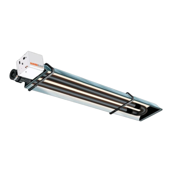
The Vision VSX Radiant Tube Heater has been tested and assessed for compliance with the following European Directives. Warning is used when failure to heed or... - Page 5 The Vision VSX Radiant Tube Heaters have an input range constitute a hazard. from 20 kW to 50 kW and are suitable for ceiling hung or wall mounted via purpose built steel supports.
-
Page 6: Health And Safety
If any of these points are not satisfied then contact should be made with the Sales Office at Nortek Global HVAC (UK) Recommended Mountain Height (m) Limited as soon as possible by telephoning 01384 489250. In the case of claims for damage, this must be signed for as Model Horizontal damaged and reported in writing within 24 hours of... - Page 7 fig. 1.b Recommended methods of heater suspension Doc No. D301024 Page 7 of 44...
-
Page 8: Clearance To Combustibles
Clearance to Combustibles The minimum clearances to combustible materials are given in the tables below. These minimum distances MUST be adhered to at all times fig. 2 Diagram illustrating the clearance to combustibles Table 1 Clearance to Combustibles VSUT 20/25/30 35/40 45/50 Above Reflector... - Page 9 1.10 Gas Connection and Supply Take care when making a gas connection to the heater not to apply excessive turning force to the internal controls. Before installation, check that the local distribution conditions, nature of gas and pressure, and adjustment of A flexible hose is installed to allow safe linear expansion the appliance are compatible.
-
Page 10: Electrical Connections
The methods shown in fig.f and fig.g are unacceptable, due to undue stress on the hose & fittings. Table 2 Gas Supply Pressures Max Supply Pressure Min Supply Pressure Nominal Pressure Gas Type Gas Category (mbar) (mbar) (mbar) I2H/I2E Nat Gas (G20) 17.5 I2E(R)B/I2Er Nat Gas (G20/25) 20/25... - Page 11 fig.5a VSX Internal Burner Wiring Diagram (Optional Webber solenoid shown in dotted) MAINS INPUT 230V/50Hz~ BODY AMBER COMBINATION LAMP VALVE 3 WAY LAMP AIR SOLENOID PRESSURE SWITCH CONTROL BL = BLUE BR = BROWN 11 12 13 14 15 16 17 18 G/Y = GREEN/YELLOW R = RED Y = YELLOW...
-
Page 12: Ventilation Requirements
Mechanical ventilation must be installed to meet a minimum of 0.5 air changes per hour using appropriately Vision VSX tube heaters can be operated as flued or unflued sized fans and interlocked with the heaters. appliances in accordance with the relevant national requirements in the country of installation. - Page 13 The maximum height unsupported above the roof line is 1.5m. Where a joint is above the roof line it should be determined that in extreme wind conditions this joint would not be over exerted. If there is any doubt then a guy wire should be used.
- Page 14 Figure 6.a. Forced Burner with Heat Exchanger (Standard Flue) For flued products of combustion and no ducted air Items Maximum flue run = 9.5m @ Ø125mm W1 127mm (5ins) to 100mm (4ins) Flue Adaptor Maximum no of bends = 2 W2 127mm (5ins) Twin Wall Flue Pipe All flues must terminate vertically.
- Page 15 Figure 6.b. Forced Burner with Heat Exchanger (No External Flue) For ducted air and products of combustion to ventilated area Maximum flue run = 9.5m @ Ø125mm Items Maximum no of bends = 2 W5 Shroud for unflued heater installation All flues must terminate vertically.
- Page 16 Figure 6.c. Forced Burner with Heat Exchanger (with Concentric Flue) For flued products of combustion and ducted air via concentric pipe. IMPORTANT NOTE This option is a type B23 flue system with ducted air and is not a room sealed balanced flue product.
-
Page 17: Technical Details
1.14 Technical Details Tables 3 - a / b Natural Gas (G20 & G25) Country Approved Gas Category 2E(R)B AT, BG, CH, CY, CZ, DK, EE, ES, FI, GB, GR, HR, IE, IT, LT, LV, NO, PT, RO, SE, SI, SK, TR LU, PL, RO Number of Injectors Gas Connection... -
Page 18: Tools Required
Assembly Instructions. 2.2.2 Brackets Tighten clamping ‘U’ bolt arrangement to tubes ONLY PLEASE READ this section prior to assembly to WHERE STATED on the assembly drawings. familiarise yourself with the components and tools you require at the various stages of assembly. Carefully open the packaging and check the contents against the parts and check list. - Page 19 2.2.6 Burner and Heat Exchanger Assembly. Slide the burner assembly onto the RIGHT HAND TUBE when viewed from above, ensuring it is fullY engaged. Slide heat exchanger onto the LEFT HAND TUBE when viewed from above, ensuring it is fully engaged. The hose connections should face vertically.
-
Page 20: Prior To Assembly
VSX3M VSX3M VSX2M VSX4M VSX2M VSX4M 30/35/40 30/35/40 20/25/30 45/50 20/25/30 45/50 M4 Full Nut M6 Washer M4 Washer M6 Full Nut M6 x 15 M6 x 35 Setpin Setpin Prior to assembly • Ensure the area in which you are working is safe and clear of obstructions. •... - Page 21 2.5.1.3 Locate and insert turbulator(s) into tube(s) ensuring the correct length and quantity are inserted into the correct tube. See assembly drawings section for location & length. CAUTION — SHARP EDGES! 2.5.2 Brackets, U Bolts and U Bends 2.5.2.1 Fit the M8 U bolts over the tubes into the holes in the bracket &...
- Page 22 2.5.3 Reflectors Remove protective film before starting. Reflectors are supplied pre-punched and are universal throughout the VSX series. 2.5.3.1 Starting at the burner end, slide the reflectors through the brackets until they are all roughly in position along the heater, referring to the assembly diagram showing overlaps.
- Page 23 2.5.3.5 Locate M4 pins, washers & nuts into holes in overlapping reflectors as shown. 2.5.4 End Caps 2.5.4.1 Using M4 setpins & washers fix the blank end cap beneath the reflector profile at the U bend end with the flanges facing outwards.
-
Page 24: Detailed Assembly Drawings
2.5.5.2 Adjust canopies so that the holes on top align with each other as detailed in the assembly instructions. Locate and fix one No.5 torque screw on every canopy overlap. 2.5.6 Canopy End Caps Locate 6 off No.5 torque screws. Position the blank canopy end cap with the end cap flanges facing inwards, beneath the canopy profile at the U bend end &... - Page 25 fig.7. VSX2M 20/25/30 Doc No. D301024 Page 25 of 44...
- Page 26 fig.8. VSX3M 30/35/40/45 Doc No.D301024 Page 26 of 44...
- Page 27 fig.9. VSX4M 45/50 Doc No. D301024 Page 27 of 44...
- Page 28 Figure 10. VSX Heater Breakdown (3 module shown) Doc No. D301024 Page 28 of 44...
-
Page 29: Commissioning Instructions
Commissioning Instructions. Gas Valve Adjustment Adjustment screw under cap to set injector pressure Injector pressure test point. Gas inlet test point. Commissioning chart for the VSX series unitary heaters Doc No. D301024 Page 29 of 44... -
Page 30: Servicing Instructions
Servicing Instructions These appliances should be serviced annually by a competent person to ensure safe and efficient operation. In exceptional dusty or polluted conditions more frequent servicing may be required. The manufacturer offers a Small Flat Head Leather Faced Pozidrive maintenance service. -
Page 31: Burner Removal
4.3 Burner Removal Step 5 Slacken the set screw on the burner support casting. Remove the burner from the radiant tube and position the burner in a safe area to prevent the burner Step 1 Isolate power and gas supplies. or components attached to the burner from falling to the ground. -
Page 32: Burner Head And Electrode Servicing
4.5 Burner Head and Electrode Servicing Step 1 Check the pepper pot burner head for contamination If necessary this can be removed. See below. This can be cleaned together with the Inside of the burner head. Step 2 The pepper pot burner head can be replaced if necessary ensuring the 5 holes on the outer ring are aligned alongside the probes. - Page 33 10° Ø76.0 15.0 +0.5 -0.0 34.0 fig. 12. Burner Head Detail Step 3 The combustion fan can now be detached. 4.6 Combustion Fan Assembly Forced Burner Step 1 Slacken jubilee clip and remove the flexible hose from the fan. Step 4 Remove the fan orifice plate and spigot.
- Page 34 4.8 Heat Exchanger Servicing Step 7 Ensure the impeller rotates freely. Step 8 Refit components. Step 1 Remove the flue connections Step 2 Slacken casing support screws and remove heat exchanger from the radiant tube. 4.7 Radiant Tube Servicing Step 3 Remove any dust and dirt from the heat exchanger Step 1 Brush any dust from the exterior of the tubes.
-
Page 35: Spare Parts
Spare Parts. Note Any spare part components that are not Required Spares. In order to aid troubleshooting and approved by the manufacturer could invalidate the servicing we recommend that the components shown in approval of the appliance and validity of the warranty. this section should be stocked. -
Page 36: Fault Finding Guide
Fault Finding Guide. START Ensure gas & electricity supplies are enabled. Turn any external timer to call for heat (if fitted). CHECK: - 1. Voltage is correct 230VAC / 50Hz. Does the Power On Is there power to the 2. Internal fuse (if fitted). light illuminate? burner? 3. - Page 37 5. Inspect tube joints and couplers for air leaks. 6. Air inlet, outlet, and emitter tubes for obstructions. 7. Seals and gaskets on forced burners. 8. Check turbulator arrangement / lengths. 9. Check correct combustion fan is fitted / HB damper pressure is set. CHECK: - 1.
-
Page 38: Replacement Parts
Replacement Parts. Step 5 Fit new burner controller. Step 6 Refit HT leads and refit burner controller to wiring 7.1 Burner Controller Replacement harness. Step 1 Slacken screw in burner lid and open the right hand Step 7 Test product and close access door. burner access door. -
Page 39: Gas Valve Replacement
7.3 Gas Valve Replacement Step 1 Remove the burner assembly as described in section 4.3 Servicing. Step 2 Open the right hand access door and detach the wiring harness and HT lead from controller. Step 3 Open the left hand access door and detach the impulse hoses from the air pressure switch. -
Page 40: Generation Codes
Step 5 The burner head assembly can be removed by firstly Step 7 Turning the housing over, remove the four screws disconnecting the silicon tube from the pressure test point, holding the rear burner plate in position. the earth cable and withdrawing the ignition lead once disconnected the from the controller. - Page 41 Ancillaries Item Description Part No. Item Description Part No. Heat Exchanger ½” BSP Gas Valve 6506 201889 Flue Adaptor ½” BSP Gas Flex Heat Exchanger 600mm 6500 VSF-DA Fresh Air Adaptor 1000mm 6500-2 Galv Suspension Chain 10m length 6515 Flue Outlet Shroud 201301 90m length 6516...
- Page 42 ANCILLARY SPARES Item Description/ Part No. Item Description Part No. Bends 45° 7075 90° 7076 Fresh Air Intake Kit Coupler 7095 Part no. FAFK-4 Extra 3M Flue 7070-SUB UK Reference Regulations Health & Safety at Work Act 1974 IEE Wiring Regulations (BS 7671) BS 6896 Specification for installation and maintenance of gas-fired overhead radiant heaters for industrial and commercial heating (2nd and 3rd family gases) BS5440 Part 1 Flueing and ventilation for gas appliances of rated input not exceeding 70kW net (1st, 2nd and 3rd family...
- Page 43 Notes Doc No. D301024 Page 43 of 44...
- Page 44 Tel: 01384 489 250 Fax: 01384 489 707 ambiradsales@nortek.com www.ambirad.co.uk Nortek Global HVAC is a registered trademark of Nortek Global HVAC Limited. Because of continuous product innovation, Nortek Global HVAC reserves the right to change product specification without due notice.
Need help?
Do you have a question about the Vision VSX and is the answer not in the manual?
Questions and answers