Advertisement
Quick Links
OWNERS MANUAL
INDIVIDUAL INFRA-RED HEATERS
VPLUS—SERIES
IMPORTANT:
ER Series
Ib101– cvr
Thoroughly read this instruction manual before perform-
ing Installation, Servicing and Maintenance procedures.
Follow all warnings or cautions included in this literature
and attached to the unit. Consult local building codes and
National Electric Code (NEC) for special requirements
TM
TM
Advertisement

Related Manuals for Ambirad VPLUS40


Summary of Contents for Ambirad VPLUS40
- Page 1 OWNERS MANUAL INDIVIDUAL INFRA-RED HEATERS VPLUS—SERIES Thoroughly read this instruction manual before perform- IMPORTANT: ing Installation, Servicing and Maintenance procedures. Follow all warnings or cautions included in this literature and attached to the unit. Consult local building codes and National Electric Code (NEC) for special requirements ER Series Ib101–...
-
Page 2: Table Of Contents
INDEX INSTALLATION INSTRUCTIONS TECHNICAL DATA (a) General Information (b) VPLUS Series Heating Models (c) Typical Arrangement of Heater PACKING AND SHIPPING INFORMATION MOUNTING CLEARANCES PRE-ASSEMBLY INSTALLATION GAS CONNECTION ELECTRICAL CONNECTION (a) Burner/Control Internal Wiring (b) Typical External Wiring VENT REQUIREMENTS & DETAILS (a) Unvented Units (b) Vented Vent (c) Horizontal Vent... -
Page 3: Technical Data
WARNING: Improper installation, adjust- ment, alteration, service or maintenance can cause property damage, injury or death. Read the instruc- tions thoroughly before installing or servicing this equipment A. INSTALLATION INSTRUCTIONS A.1 TECHNICAL DATA Heaters may be suspended either hori- zontal or at an angle, or may be wall General Information: mounted. -
Page 4: Mounting Clearances
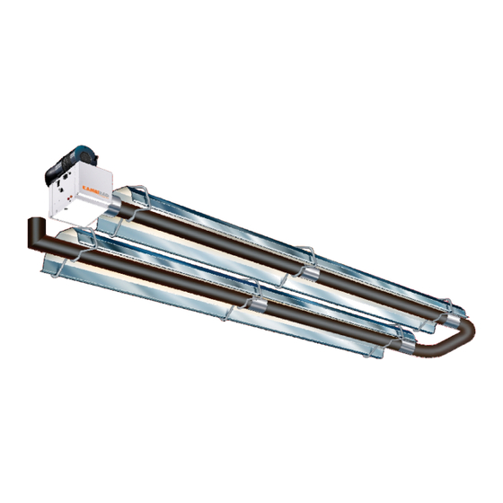
Minimum Clearances to Combustible. Model(s) Input B B1 C1 C2 C3 D1 D2 E Shipping packages for individual projects will be boxed and crated as outlined in the specific bill of lading. VPLUS40 41,500 Suggested Mounting Height Above Floor. 80,000 VPLUS80... - Page 5 Each heating unit has two types of emitter tubes. The first tube section, connected to the burner, will be Calcoat, silver in color marked with yellow paint. The remaining tubes are mild steel marked with blue paint. Exception: 175,000 through 225,000 Btu units require a sec- ond section of Calcoat, 20ft total, steel tube connected together by a high tem- perature coupling, see Figure 1, pg.
- Page 6 40 to 150,000 btu 170 to 225,000 btu Page 6...
-
Page 7: Installation
A.6 GAS CONNECTION (cont) Black Bulb Thermostats controlling up to 10 heaters per thermostat for zone control It is essential to provide some flexibility in the of the heated area. final gas connection preferably by use of an approved flexible gas connector or stainless (Control Panels are not A.G.A/CSA de- steel expansion loop. - Page 8 Page 8...
- Page 9 4¼” Page 9...
-
Page 10: Gas Connection
10. INSTALLATION CHECK OUT attempted. After 2 further attempts at igni- AND START UP. tion the control unit will ‘lock-out’, the ‘power on’ lamp will remain illuminated and the fan will continue to run. To reset after Inspect installation and ensure that it has ‘lockout’... - Page 11 11. COMMISSIONING INSTRUCTIONS. Check installation has Ensure gas & electricity Disconnect gas hose from been carried out to these supplies are enabled. burner. instructions. Remove burner from tube and inspect burner head. See servicing instructions. Reconnect gas hose. Open Open control housing and Replace burner on tube isolating valve.
- Page 12 B SERVICING AND MAINTENANCE INSTRUCTIONS B1. Servicing 1.2 Burner Removal Step 5 Remove the burner and position the burner in a safe area to prevent the burner or components attached to the burner Step 1 Isolate mains electric and gas sup- from falling to the ground.
- Page 13 Step 2 The gas injector can be inspected and Step 3 The condition of the igniter assembly replaced if contaminated or blocked. can be checked for deterioration. However, we advise replacement at each service to ensure When replacing the gas injector ensure approved thread sealant is used.
- Page 14 Step 7 Ensure the impeller rotates freely. 1.5 Combustion Fan Assembly Step 1 If ducted air is fitted, slacken jubilee clip Step 8 Refit components. and remove the flexible hose from the fan. 1.6 Radiant Tube Servicing Step 1 Brush any dust from the exterior of the tubes.
- Page 15 B2. Fault Finding Ensure gas & electricity supplies are enabled. Check: 1. Ignition controller 2. Red neon Does the RED Is there power on neon the burner? illuminate? Check: 1. Operation of any thermostat 2. Check any external fuses Check: Check: 1.
-
Page 16: Electrical Connection
B3. Replacement of Components 3.1 Burner Controller Replacement 3.2 Air Pressure Switch Replacement Step 1 Slacken screw in burner lid and open the Step 1 Open the left hand door and disconnect right hand burner access door. the two silicone impulse tubes and the 3 cables. Step 2 Disconnect burner controller from the burner harness. -
Page 17: Servicing
Step 6 Detach the two screws holding the front 3.3 Gas Valve Replacement of the gas valve. Step 1 Remove the burner assembly as de- scribed in the Servicing Sections. Step 2 Open the right hand access door and detach the burner controller from the wiring harness. -
Page 18: Spare Parts
B4. Spare Parts ITEM PHOTO DESCRIPTION PART NUMBER IGNITION CONTROLLER 3256-11 GAS VALVE 201706 BURNER ON AMBER NEON 2181 MAINS ON RED NEON 2176 GAS INJECTOR See table A BURNER BODY 200358 BURNER HEAD See table A IGNITOR ASSEMBLY 201284 40 - 50 - 200420 JET CARRIER 170 - 225 - 201630... - Page 19 Page 19...
- Page 34 VPLUS 170,200 AND 225 ITEM DESCRIPTION PART# IGNITION CONTROLLER GAS VALVE BURNER ON AMBER NEON MAINS ON RED NEON GAS INJECTOR BURNER BODY BURNER HEAD IGNITOR ASSEMBLY JET CARRIER COMBUSTION FAN VACUUM/PRESSURE SWITCH GASKET SET BURNER HEAD WIRING HARNESS Page 34...
- Page 35 Page 35...
- Page 36 Ambi-Rad Limited P.O. Box 617 is the registered Fishers, Indiana 46038 Trademark of Ambi-Rad Limited. Telephone 317-577-0337 Facsimile 317-842-3989 Due to continuous product Website www.ambi-radusa.com innovation, Ambi-Rad reserves For the Distributor Nearest to you call the right to change product specifi- 1-888-330-4878 cation without due notice.
Need help?
Do you have a question about the VPLUS40 and is the answer not in the manual?
Questions and answers