Table of Contents
Advertisement
Advertisement
Table of Contents

Related Manuals for Ambirad VPlus40


Summary of Contents for Ambirad VPlus40
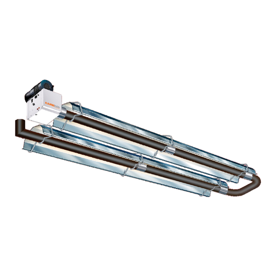
- Page 1 Vision Range VPLUS OWNERS MANUAL WARNING: Improper installation, adjustment, alteration, service or maintenance can cause property damage, injury or death. Read the installation, operating and maintenance instructions thoroughly before installing or servicing this equipment.
-
Page 2: Table Of Contents
Introduction. Welcome to the new range of high efficiency and servicing is undertaken on radiant tube AmbiRad VPLUS infra-red heaters. Local heaters specified in these instructions, due care regulations may vary and it is the installer’s and attention is required to ensure that working... -
Page 3: Packing And Shipping Information
The unit shall be electrically grounded in * Connector must comply with ANSI Z21.24/CSA 6.10. accordance with National Electric Code Shipping packages for individual projects will be ANSJJNFPA 70-1987. boxed and crated as outlined in the specific bill The heater may be installed in aircraft of lading. -
Page 4: Wall Mounting
The suggested mounting heights for AmbiRad heaters are given in table 1 below. Wall Mounting These radiant tube heaters can be wall mounted using the appropriate bracket. When using the wall mounting brackets the heater must be inclined at an angle between 35°... - Page 5 Figure 2 Clearance to Combustibles. The minimum clearances to combustible materials are given in the tables below. These minimum distances MUST be adhered to at all times. 0° to 55°...
- Page 6 Figure 3. Correct orientation of Ball Valve Gas Connection and Supply WARNING: Before installation, check that the local distribution conditions, nature of gas and pressure, and adjustment of the appliance are compatible. Gas Flow The gas connection on the heater is ½”N.P.T external thread.
-
Page 7: Electrical Connections
WARNING: FIRE OR EXPLOSION HAZARD - Expansion of the radiant pipe occurs with each firing cycle causing the burner to move with respect to the gas line. This can result in a gas leak producing an unsafe condition. It is therefore essential to provide some flexibility in the final gas line connection - preferably by use of an approved armoured flexible connector or stainless steel expansion loop as shown in the drawings. - Page 8 Figure 5.b Typical VPLUS range Wiring Connections Switch with Fuse Fan plugs into burner Figure 6. Internal Burner Wiring Diagram. BROWN VACUUM SWITCH SOLENOID VALVE N.C. N.O. GREEN VALVE J.S.T. BURNER POWER INPUT GREEN WHITE WHITE BURNER POWER WHITE LAMPS BROWN BROWN PURPLE...
-
Page 9: Vertical Venting
120v 1ph 60Hz local codes. Recommended terminals are 1.8 Vent Requirements and Details AmbiRad V0700 for 4” and V0800 for 6” vent. 1.8.1 Unvented units Maximum length of vent is 25ft with 2 - 90° long radius elbows. Heaters... - Page 10 A fresh air duct of 4” dia. Should be Figure 8.a Vertical Venting. installed from the fresh air to the air CODE APPROVED VENT intake connection THROUGH ROOF housing. A flexible jointing piece should be installed at the fan connection with hose clamps to ROOF SEAL facilitate expansion and contraction.
-
Page 11: Technical Details
100,000 201063-23 201007-21 VPLUS100 80,000 201063-29 201007-18 VPLUS80 60,000 201063-45 201007-15 VPLUS60 41,500 201063-18 201007-13 VPLUS40 Combustion Fan Pressure Min. Heater Length Max. Heater Length Details Switch Burner Size Orifice Fan Type Part No. U (ft) S (ft) U (ft) S (ft) Part No. -
Page 13: Assembly Instructions
2. Assembly Instructions. PLEASE READ this section prior to Please ensure that all packaging is assembly to familiarise yourself with the disposed of in a safe environmentally components and tools you require at the friendly way. various stages of assembly. Carefully open the packaging and check the contents against the For your own safety we recommend the parts and check list. -
Page 14: Couplers
• Type ‘F’ are fixed reflector brackets. 2 x SCREWS TIGHTENED TO FIX REFLECTOR A standard stainless steel 4” coupling which is • Type ‘S’ are sliding reflector brackets. used for all other fixings. Slide the coupler over the tube ensuring that the rivet stop has butted up to the tube ends. -
Page 15: Burner/Fan Assembly
180° Bend 2.2.5 Reflectors. After removing the protective plastic coating, slip the reflectors through the hanger brackets until they overlap each other. End Caps (optional ) All reflectors must be positioned/ attached to the brackets exactly as detailed in the assembly drawings. The first and second reflector are fixed at the point F by a type F reflector support bracket 15”... - Page 16 Figure 9. VPLUS Heater Assembly: Model Linear 40-S10.
- Page 17 Figure 10. VPLUS Heater Assembly: Model Linear 40-S20, 60-S20 and 80-S20.
- Page 18 Figure 12. VPLUS Heater Assembly: Model Linear 40-S30, 60-S30, 80-S30 and 100-S30.
- Page 19 Figure 13. VPLUS Heater Assembly: Model Linear 80-S40, 100-S40, 125-S40 and 150-S40.
- Page 20 Figure 14. VPLUS Heater Assembly: Model Linear 100-S50, 125-S50, 150-S50, 170-S50, and 200-S50...
- Page 21 Figure 15. VPLUS Heater Assembly: Model Linear 125-S60, 150-S60, 170-S60 and 200-S60...
- Page 22 Figure 16. VPLUS Heater Assembly: Model Linear 150-S70, 170-S70 and 200-S70.
- Page 23 Figure 17. VPLUS Heater Assembly: Model Linear 170-S80 and 200-S80...
- Page 24 Figure 18. VPLUS Heater Assembly: Model Linear 40-U20 and 80-U20. 3' 3"...
- Page 25 Figure 19. VPLUS Heater Assembly: Model Linear 80-U40, 100-U40, 125-U40 and 150-U40. 3' 3"...
- Page 26 Figure 20. VPLUS Heater Assembly: Model Linear 125-U60, 150-U60, 170-U60 and 200-U60 3' 3"...
- Page 27 Figure 21. VPLUS Heater Assembly: Model Linear 170-U80 and 200-U80 3' 3"...
-
Page 28: Start Up Procedure
3. Start Up Instructions. These appliances should be commissioned by a qualified mechanical contractor. Tools Required. The following tools and equipment are advisable Suitable alternative tools may be used. to complete the tasks laid out in this manual. Large Adjustable Small Flat Leather Phillips... -
Page 29: Servicing Instructions
should attempt to relight and if the gas valve With the heater running normally, pull off the has been left off ‘lock-out’ should occur silicone rubber tube connecting the vacuum indicated by the ‘power on’ lamp being switch to the combustion chamber. Within 4 illuminated and fan running, but the ‘burner on’... -
Page 30: Tools Required
4. Servicing Instructions. These appliances should be serviced annually by a competent person to ensure safe and efficient operation. In exceptional dusty or polluted conditions more frequent servicing may be required. Servicing work should be carried out by a qualified me- chanical contractor. -
Page 31: Burner Removal
burner or components attached to the burner 4.3 Burner Removal from falling to the ground. Step 1 Isolate power and gas supplies. Step 2 Unplug the power connectors. 4.4 Burner Gas Injector Servicing Step 1.a Remove the burner support casting Step 3 Detach the gas supply as shown below, and gasket. -
Page 32: Burner Head And Electrode Servicing
the two screws and separating the igniter lead connectors. Step 3 Reconnect ignition leads and silicone tube to test nipple. Refit gasket and support casting. Step 4 Refit the electrode assembly and ensure the connections are secure to prevent incorrect sparking of the spark electrode. -
Page 33: Radiant Tube Servicing
Step 2 Remove fan screws and unplug from Step 7 Refit components. burner box. 4.8 Reflector Servicing The condition of the reflectors should be noted. If necessary the reflectors can be cleaned with a mild detergent. This can significantly improve the efficiency of the appliance. -
Page 34: Spare Parts
5. Spare Parts. Required Spares Note Any spare part components that are not approved by AmbiRad could invalidate In order to aid troubleshooting and servicing we the approval of the appliance and validity of the recommend that the components shown in this warranty. -
Page 35: Troubleshooting Guide
6. Troubleshooting Guide. Ensure gas & electricity supplies are enabled. Check: 1. Ignition controller 2. Red neon faulty Does the RED Is there power neon to the burner? illuminate? Check: 1. Operation of any thermostat 2. Any external fuses 3. Correct voltage is supplied Check: 1. -
Page 36: Replacing Parts
7. Replacing Parts. 7.2 Air Pressure Switch Replacement Turn off gas and any electrical supplies to the heater before starting repair work. Step 1 Open left hand door. Disconnect the two silicone impulse tubes. 7.1 Burner Controller Replacement Step 1 Slacken screw in burner lid and open the right hand burner access door. -
Page 37: Gas Valve Replacement
7.3 Gas Valve Replacement Step 6 Detach the two screws holding the front of the gas valve. Step 1 Remove the burner assembly as described in the Servicing Sections. Step 2 Open the right hand access door and detach the burner controller from the wiring harness. - Page 38 Notes.
- Page 39 Notes.
-
Page 40: User And Operating Instructions
8. User & Operating Instructions. AmbiRad is the manufacturer of a series of tubular infra-red heaters designed for overhead heating of industrial and commercial buildings. Individual heating units are suspended from the roof or mounted at an angle on the wall This appliance must only be installed by qualified craftsmen in accordance with the requirements of local and National Codes.
Need help?
Do you have a question about the VPlus40 and is the answer not in the manual?
Questions and answers