Table of Contents
Advertisement
Quick Links
Advertisement
Table of Contents

Related Manuals for Ambirad Vision Range VSXUS


Summary of Contents for Ambirad Vision Range VSXUS
- Page 1 WARNING: Improper installation, adjustment, alteration, service or maintenance can cause property damage, injury or death. Read the installation, operating and maintenance instructions thoroughly before installing or servicing this equipment.
-
Page 2: Table Of Contents
Introduction. Welcome to the new range of high efficiency and attention is required to ensure that working AmbiRad VSXUS infra-red heaters. Local at height regulations are adhered to at the regulations may vary and it is the installer’s mounting heights specified. -
Page 3: Installation Requirements
Heaters include: Options: Burner/Control The suggested mounting heights for AmbiRad Heat Exchanger heaters are given in table 1 below. Radiant Tubes Reflectors/Canopies Brackets... - Page 4 Figure 1. Recommended Methods of Heater Suspension.
-
Page 5: Clearance To Combustibles
IMPORTANT: Clearance to Combustibles. stated clearance combustibles The minimum clearances to combustible represents a surface temperature of 90°F (32°C) materials are given in the tables below. above room temperature. Building material with These minimum distances MUST be adhered to a low heat tolerance may be subject to at all times. - Page 6 Gas Connection and Supply Figure 3. Correct orientation of Ball Valve WARNING: Before installation, check that the local distribution conditions, nature of gas and pressure, and adjustment of the appliance are compatible. Gas Flow The gas connection on the heater is ½”N.P.T external thread.
-
Page 7: Electrical Connections
WARNING: FIRE OR EXPLOSION HAZARD - Expansion of the radiant pipe occurs with each firing cycle causing the burner to move with respect to the gas line. This can result in a gas leak producing an unsafe condition. It is therefore essential to provide some flexibility in the final gas line connection by use of an approved armoured flexible... - Page 8 Figure 6. Internal Burner Wiring Diagram. BROWN VACUUM SWITCH SOLENOID VALVE N.C. N.O. GREEN VALVE J.S.T. BURNER POWER INPUT GREEN WHITE WHITE BURNER POWER WHITE LAMPS BROWN BROWN PURPLE BLACK MAIN J.S.T. YELLOW GREY BROWN If any of the original wire as supplied with the appliance must be replaced, it must be replaced with wiring material having a temperature rating of at least 220°F/105°C Figure 7.
-
Page 9: Unvented Units
The location of the fresh air duct inlet must be through side walls. Recommended terminals where it will receive dust free clean air. are AmbiRad V0700 for 4” and V0800 for 6”. An inlet cap with bird screen must be fitted at Distances from adjacent public walkways, the inlet of the duct. -
Page 10: Vent & Combustion Air Inlet
Figure 8.a Fresh Air Ducted Intake. 4" O.D. PIPE MAX LENGTH = 25'-0" WITH 2-90° LONG RADIUS BENDS 90° BEND 4" O.D. HIGH TEMP. FLEXIBLE DUCT CLAMPS REFLECTOR HEAT EXCHANGER Figure 8.b Wall Terminal Intake Kit. TERMINAL WALL INLET WITH SEAL JOINTS WITH BIRD SCREEN SILICONE OR DUCT TAPE... - Page 11 Figure 8.c Vertical Venting. CODE APPROVED VENT THROUGH ROOF ROOF SEAL SEAL JOINTS WITH HIGH TEMPERATURE SILICONE 4" O.D. OR 6" O.D. FLUE 12'-0" 12'-0" (APPROXIMATE MAXIMUM DIMENSIONS) 4" TO 6"DIA. ALUMINIUM ADAPTER (REQUIRED ONLY FOR 6" DIA. VENT) 4" O.D. HIGH TEMP. FLEXIBLE DUCT CLAMPS REFLECTOR...
- Page 12 Option 1 - Figure 8.e. Forced Burner with Heat Exchanger (Standard Vent) For vented products of combustion and no ducted air Products of combustion Inlet Firing tube Products of combustion If heaters are installed with no vent the ventilation instructions detailed in section 1.8 must be applied.
- Page 13 Option 2 - Figure 8.f. Forced Burner with Heat Exchanger (No External Venting) For ducted air and products of combustion to ventilated area Fresh Products of combustion to ventilated area Firing tube Products of combustion Forced Burner if heaters are installed with no vent the ventilation instructions detailed in section Heat Exchanger 1.8 must be applied.
- Page 14 Option 3 - Figure 8.g. Forced Burner with Heat Exchanger (with Concentric vent) For vented products of combustion and ducted air via concentric pipe Products of combustion Fresh Air Inlet Fresh Products of combustion Firing Tube Products of combustion if heaters are installed with no vent the Concentric Vent Terminal ventilation instructions detailed in section 4ins Flexible to concentric vent...
-
Page 15: Technical Details
1.10 Technical Details Table 4 - Technical Details. All heaters to run on Natural Gas (G20) No of Injectors ½” N.P.T nipple. Gas Connection 120 volt 1 phase 60Hz Electrical Supply 4” or 6” Vent size (in) 120 volt 1 phase 60Hz Unitary Fan Motor Details 1.2A MAX Current Rating... -
Page 16: Identification Check List
Identification check list COLOUR CODE VSX90 VSX140 COLOUR CODE VSX90 VSX140 Inner End Caps Burner Outer Heat Canopy Exchanger End Caps Tubes U Bend Inner Reflectors Turbulators Outer Couplers Canopy Full Nut Brackets Washer Mudwasher No.5 Torque Screw Washer M6 x 15 Full Nut Setpin M6 x 35... -
Page 17: Prior To Assembly
Prior to assembly • Ensure the area in which you are working is safe and clear of obstructions. • Identify with the components in the check list and in which order they will be assembled. • Arrange the trestles* in a straight line to allow for length of tubes. •... - Page 18 Working at the opposite ends of the tubes to the burner, locate & position two couplers so that the socket heads are facing outwards & the pre-fitted bolts in the couplers line up with the locating holes in the tubes. Do not fully tighten at this stage.
- Page 19 Slide 2nd bracket to line up with innermost slotted hole in 1st reflector, & bolt together using M6 x 35mm pins, washers & nuts. Bolt 1st & 2nd reflectors together using end elongated holes in each. Repeat this procedure referring assembly diagram for quantities used on specific models, but noting that the final bracket is not bolted to the reflector.
-
Page 20: Assembly Instructions
2.4.5 CANOPIES Remove protective film before starting. Slide the outer canopies over the reflectors from the U bend end ensuring correct location in re- flector profile. Line up burner end canopy flush with burner end reflector. Overlap canopies as shown in the assembly diagram. CAUTION —... - Page 21 Figure 9. VSXUS Heater Assembly 2.4.8 Detailed Assembly Drawings Please note the heater type, length and reference number from the delivery/advice note The following pages show the technical before identifying the correct model drawing. dimensional details of the VSXUS range of heaters.
- Page 23 Figure 10. VSXUS Heater Breakdown (3 module VSXUS140 shown)
- Page 24 3. Start Up Instructions. These appliances should be commissioned by a qualified mechanical contractor. Tools Required. The following tools and equipment are advisable Suitable alternative tools may be used. to complete the tasks laid out in this manual. Large Adjustable Small Flat Leather Phillips...
- Page 25 should attempt to relight and if the gas valve With the heater running normally, pull off the has been left off ‘lock-out’ should occur silicone rubber tube connecting the vacuum indicated by the ‘power on’ lamp being switch to the combustion chamber. Within 4 illuminated and fan running, but the ‘burner on’...
-
Page 26: Servicing Instructions
4. Servicing Instructions. These appliances should be serviced annually by a competent person to ensure safe and efficient operation. In exceptional dusty or polluted conditions more frequent servicing may be required. Servicing work should be carried out by a qualified me- chanical contractor. - Page 27 4.3 Burner Removal Step 1 Isolate power and gas supplies. Step 2 Unplug the power connectors. Step 5 Slacken the set screw on the burner support casting to enable the burner to be removed from the radiant tube. Step 6 Remove the burner and position the burner in a safe area to prevent the burner or components attached to the burner Step 3 Detach the gas supply as shown below,...
- Page 28 replaced ensuring the 5 holes on the outer ring are aligned alongside the probes. Step 2 The gas injector can be inspected and replaced if contaminated or blocked. Step 3 The condition of the igniter assembly can be checked for deterioration. However, we When replacing the gas injector ensure advise replacement at each service to ensure approved thread sealant is used.
-
Page 29: Turbulators
4.6 Combustion Fan Assembly Step 1 If ducted air is fitted, slacken hose clamp and remove the flexible hose from the fan. Step 7 Ensure the impeller rotates freely. Step 8 Refit components. Step 2 Remove fan screws and unplug from 4.7 Radiant Tube Servicing burner box. -
Page 30: Heat Exchanger Servicing
If necessary the reflectors can be cleaned with a mild detergent. This can significantly improve the efficiency of the appliance. 4.10 Sweeping of Vent Inspect the fresh air inlet duct and vent to ensure they are free from any blockage or obstruction. -
Page 31: Spare Parts
5. Spare Parts. Required Spares Note Any spare part components that are not approved by AmbiRad could invalidate In order to aid troubleshooting and servicing we the approval of the appliance and validity of the recommend that the components shown in this warranty. -
Page 32: Troubleshooting Guide
6. Troubleshooting Guide. Ensure gas & electricity supplies are enabled. Check: 1. Ignition controller 2. Red neon faulty Does the RED Is there power neon on the burner? illuminate? Check: 1. Operation of any thermostat 2. Any external fuses 3. Correct voltage is selected Check: 1. -
Page 33: Replacing Parts
7. Replacing Parts. 7.2 Air Pressure Switch Replacement Turn of gas any electrical supplies to the heater before starting repair work.. Step 1 Open left hand door. Disconnect the two silicone impulse tubes. 7.1 Burner Controller Replacement Step 1 Slacken screw in burner lid and open the right hand burner access door. -
Page 34: Gas Valve Replacement
7.3 Gas Valve Replacement Step 6 Detach the two screws holding the front of the gas valve. Step 1 Remove the burner assembly as described in the Servicing Sections. Step 2 Open the right hand access door and detach the burner controller from the wiring harness. - Page 35 THIS PAGE HAS INTENTIONALLY BEEN LEFT BLANK.
-
Page 36: User And Operating Instructions
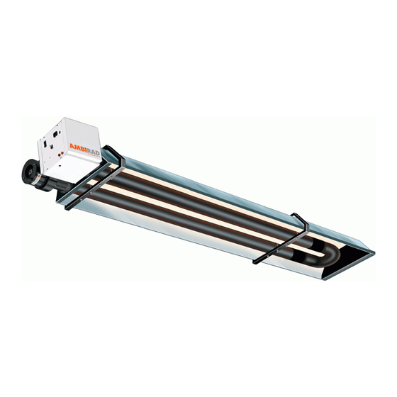
8. User & Operating Instructions. AmbiRad is the manufacturer of a series of tubular infra-red heaters designed for overhead heating of industrial and commercial buildings. Individual heating units are suspended from the roof or mounted at an angle on the wall This appliance must only be installed by qualified craftsmen in accordance with the requirements of local and National Codes.
Need help?
Do you have a question about the Vision Range VSXUS and is the answer not in the manual?
Questions and answers