
Related Manuals for Cybernet CyberMed H22


Summary of Contents for Cybernet CyberMed H22
- Page 1 CyberMed H22/N22 All-in-one Medical Panel PC User’s Manual Rev: V1.1 Copyright©,2012. All rights reserved All other brand names are registered trademarks of their respective owners.
- Page 2 The information contained in this document is subject to change without notice WMP-226/227 User’s Manual...
- Page 3 Version Change History Date Version Description Remark 2012/7/6 First release Cosa Huang 2012/8/20 Update battery spec James.Chiu CyberMed H22/N22 User’s manual...
- Page 4 Intel is a trademark or registered trademark of Intel Corporation. Microsoft Windows is a registered trademark of Microsoft Corporation. Winbond is a registered trademark of Winbond Electronics Corporation. All other product names or trademarks are properties of their respective owners. CyberMed H22/N22 User’s manual...
- Page 5 To avoid risk of electric shock, this equipment must only be connected to a supply mains with protective earth. Do not modify this equipment without authorization of the manufacturer. CyberMed H22/N22 User’s manual...
-
Page 6: Safety Instructions
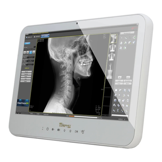
Safety Instructions Intended use The CyberMed H22/N22 is intended to serve as a medical monitor which is designed for general purpose for hospital environment and for diagnosis. It could be used for Surgical, Radiology, PACS (Picture Archiving Communication Systems), LIS (Lab Information Systems) and Electronic Medical Record purpose. - Page 7 If your hands are wet, do not touch the plug. Use your thumb and index finger, grip firmly on the power cord to disconnect from the electrical socket. By pulling the power cord, may result in damaging it. CyberMed H22/N22 User’s manual...
- Page 8 Unless proper ventilation is present, do not place unit in an enclosed area; such as a built-in shelf. Keep a minimum distance of 10 cm between the display unit and wall. viii CyberMed H22/N22 User’s manual...
- Page 9 (e) If the power cord or plug is damaged. (f) When the functions of the unit are dysfunctional. When replacement parts are needed for the medical panel PC unit, make sure service technicians use replacement parts specified by the manufacturer, or those with the CyberMed H22/N22 User’s manual...
- Page 10 The mark on electrical and electronic products only applies to the current European Union Member States. CyberMed H22/N22 User’s manual...
- Page 11 IEC 60601-1-1. The unit is for exclusive interconnection with IEC 60601-1 certified equipment in the patient environment and IEC 60XXX certified equipment outside of the patient environment. If in doubt, consult the technical services department or your local representative. CyberMed H22/N22 User’s manual...
-
Page 12: Contact Information
C) Caution: This adapter Sinpro MPU101-105 is a forming part of the medical device Contact information: Address: 5 Holland, Bldg. 201 Irvine, CA92618 U.S.A. TEL: (888)834-4577 E-Mail: sales@cybernetman.com CyberMed H22/N22 User’s manual... -
Page 13: Table Of Contents
B. L type Stand (optional kit) ....51 C. Battery Pack Specifications....52 D. Change Win Xp resolution to 1920*1080 . 53 E. How to disable battery when system hang up -CyberMed H22/N22 ........ 54 F. Scrap Computer Recycling ..... 55 xiii CyberMed H22/N22 User’s manual... -
Page 15: Introduction
Introduction Product Description The CyberMed H22/N22 Medical Panel PC are based on Intel 2nd generation Core i processor which can deliver faster graphic with higher CPU performance. It accommodates one 2.5” SATA II hard disk drive and up to 8GB DDR3 SODIMM. -
Page 16: Package List
Before you begin installing your Medical Station, please make sure that the following items have been shipped: • The CyberMed H22/N22 Medical Panel PC unit • One CD containing user manual, chipset drivers • Power Adapter x 1 (Mf:Sinpro, type/model: MPU101-105) •... -
Page 17: Features
HDD Anti-vibration mechanism Low noise Smart fan solution(CyberMed H22) Fanless Solution (CyberMed N22) Anti-bacteria (MRSA) plastic housing Built-in Battery backup function (option) optional Video Graphic card (CyberMed H22 only) CyberMed H22/N22 User’s manual... -
Page 18: Specifications
Model Name AUO M215HW03 V1 Display Type 21.5” color TFT LCD Max. Resolution 1920 x 1080 (Full HD) Contrast Ratio 1000 : 1 (Typ) Pixel Pitch (um) 248.25 (per one triad) × 248.25 Luminance (cd/m2) 250 (TYP) CyberMed H22/N22 User’s manual... - Page 19 VESA 75/100mm Construction 3mm ABS + PC TYPE Plastic housing Dimension (WxHxD) 540 x 375 x 78 mm CyberMed H22: 6.5kg (w/o power adapter) Net Weight CyberMed N22: 7.0kg (w/o power adapter) Packing Filler Environmental Specifications Operating: 0°C to 40°C (32°F ~104°F) Temperature Storage, Transportation: -20°C to 60°C (-4°F...
-
Page 20: Guidance And Manufacturer's Declaration - Electromagnetic Emissions
The model CyberMed H22/N22 is intended for use in the electromagnetic environment specified below. The customer or the user of the model CyberMed H22/N22 should assure that it is used in such an environment. Emissions test Compliance Electromagnetic environment –... - Page 21 The model CyberMed H22/N22 is intended for use in an electromagnetic environment in which radiated RF disturbances are controlled. The customer or the user of the model CyberMed H22/N22 can help prevent electromagnetic interference by maintaining a minimum distance between portable and mobile RF communications equipment...
-
Page 22: Guidance And Manufacturer's Declaration - Electromagnetic Immunity
Guidance and manufacturer’s declaration – electromagnetic immunity The model CyberMed H22/N22 is intended for use in the electromagnetic environment specified below. The customer or the user of the model CyberMed H22/N22 should assure that it is used in such an environment. Immunity test IEC 60601... -
Page 23: Guidance And Manufacturer's Declaration - Electromagnetic Immunity
Guidance and manufacturer’s declaration – electromagnetic immunity The model CyberMed H22/N22 is intended for use in the electromagnetic environment specified below. The customer or the user of the model CyberMed H22/N22 should assure that it is used in such an environment. - Page 24 If the measured field strength in the location in which the model CyberMed H22/N22 is used exceeds the applicable RF compliance level above, the model CyberMed H22/N22 should be observed to verify normal operation. If abnormal performance is observed, additional measures may be necessary, such as reorienting or relocating the model CyberMed H22/N22.
-
Page 25: Cleaning/Disinfecting
Cleaning/Disinfecting Steps: 1. Wipe the CyberMed H22/N22 with a dry clean cloth. 2. Prepare agent per manufacturer’s instructions or hospital protocol. Cautions: Do not immerse or rinse the CyberMed H22/N22 and its peripherals. If you accidentally spill liquid on the device, disconnect the unit from the power source. -
Page 26: Getting Started
USB-CD/DVD drive, turn on computer power, keep on pressing “F11” key, go into BIOS quick boot menu, select “USB-CD ROM”, WAIT FOR 20 SECONDS, then press enter, system OS will boot up from USB-CD/DVD drive directly. CyberMed H22/N22 User’s manual... -
Page 27: Dimension
Dimension CyberMed H22 CyberMed H22/N22 User’s manual... - Page 28 CyberMed N22 CyberMed H22/N22 User’s manual...
-
Page 29: System View
2. Power (with LED status indicator: ON: Green, OFF: dark) 3. Volume adjustment (-) 4. Volume adjustment (+) 5. Brightness (-) 6. Brightness (+) 7. LCD on/off (with LED status indicator: LCD ON: dark, LCD OFF: CyberMed H22/N22 User’s manual... - Page 30 8. Clean me (with LED status indicator: ON: Yellow, OFF: dark) a. Keep on contacting 5 seconds to active b. keep contacting 5 seconds to release c. auto release after 60 seconds I/O parts (CyberMed H22/N22) CyberMed H22/N22 User’s manual...
-
Page 31: Disconnect Device
Disconnect Device Unplug the power cord from the power adapter jack to disconnect the device. CyberMed H22/N22 User’s manual... -
Page 32: Bios Setup
<PgUp> and <PgDn> keys to change entries, <F1> for help and <Esc> to quit. When you enter the Setup utility, the Main Menu screen will appear on the screen. The Main Menu allows you to select from various setup functions and exit choices. CyberMed H22/N22 User’s manual... - Page 33 This section provides information on the BIOS information, Memory information, and LAN MAC information System Language Choose the BIOS default language. System Date/Time Set the system date/time. Use the <Tab> key to switch between data/time elements. CyberMed H22/N22 User’s manual...
- Page 34 Enables or Disables PCI Device to Generate PERR#. SERR# Generation Enables or Disables PCI Device to Generate SERR#. Relaxed Ordering Enables or Disables PCI Express Device Relaxed Ordering. Extended Tag If ENABLED allows Device to use 8-bit Tag field as a requester. CyberMed H22/N22 User’s manual...
-
Page 35: Acpi Settings
Hyper-Threading Technology) and Disabled for other OS (OS optimized for Hyper-Threading Technology) Core-Multi Processing Enable or Disable Core-Multi Processing mode. Execute Disable Bit XD can prevent certain classes of malicious buffer overflow attacks when combined with a supporting OS (Windows CyberMed H22/N22 User’s manual... -
Page 36: Ide Configuration
>>Hardware: Spread is controlled by chip; >>Software: Spread is controlled by BIOS. TV1 Standard TV2 Standard Active LFP Select the Active LFP Configuration. No LVDS:VBIOS does not enable LVDS. INT-LVDS:VBIOS enables LVDS driver by Integrated encoder. CyberMed H22/N22 User’s manual... - Page 37 Set Parameters of Serial Port 2 (COM D). Serial Port 3 Configuration Set Parameters of Serial Port 3 (COM E). Serial Port 4 Configuration Set Parameters of Serial Port 4 (COM F). Serial Port Console Redirection Serial Port Console Redirection. CyberMed H22/N22 User’s manual...
- Page 38 Chipset Host Bridge/South Bridge This screen provides information on Host Bridge/South Bridge parameters. CyberMed H22/N22 User’s manual...
-
Page 39: Interrupt 19 Capture
Option ROM Messages Sets display made for option ROM. Interrupt 19 Capture Enables or disables Option ROMs to Trap Int 19. Boot Option Priorities Specifies the sequence of loading the operating system from the installed hard drives. CyberMed H22/N22 User’s manual... - Page 40 Security Enables or disables the security chip. It is recommended that you use this function with the Administrator/User password. CyberMed H22/N22 User’s manual...
-
Page 41: Restore Defaults
Save as User Defaults Save the changes done so far as User Defaults. Restore User Defaults Restore the User Defaults to all the setup options. EFIGUI_FLASH Press <Enter> to execute the simple EFI GUI Flash Program. CyberMed H22/N22 User’s manual... -
Page 42: Appendix
This appendix gives the definitions and shows the positions of jumpers, headers and connectors. All of the configuration jumpers on CyberMed H22/N22 are in the proper position. Note: Some of jumpers or connectors will be removed base on system configuration. - Page 43 ELO type 5-6,7-8 JP8– Panel Power Selection Description Jumper Setting +5VS (for 17"/19"/21.5”) 1-2,3-4 (default) +3.3VS (for 10"/12"/15") 5-6,7-8 JP9 –TPM Settings Description Jumper Setting Clear ME RTC registers Keep ME RTC registers OPEN (default) CyberMed H22/N22 User’s manual...
- Page 44 Jumper Setting SATA DOM 1-2 ---power +5V SATA 2-3(default)--- GND JP13 – COM1 Function Selection Description Jumper Setting RS-232 5-6, 9-11, 10-12, 15-17, 16-18(default) RS-422 3-4, 7-9, 8-10, 13-15, 14-16, 21-22 RS-485 1-2, 7-9, 8-10, 19-20 CyberMed H22/N22 User’s manual...
- Page 45 PJ5 – HDD Power Connector Pin # Signal Description +12V Ground Ground PJ6 – HDD Power Connector Pin # Signal Description +12V Ground Ground PJ7 – Battery Connector Pin1 Pin # Signal Description BATT+ CyberMed H22/N22 User’s manual...
- Page 46 BATT- BATT- PJ8 – Power Jack Connector Pin # Signal Description DC In DC In Ground Ground Ground J5,J6,J7 – Internal USB +3.3V Interface Pin # Signal Description +3.3VS Data - Data + Ground Ground CyberMed H22/N22 User’s manual...
- Page 47 Backlight Adjust Backlight Enable Ground Ground J9 –Resistor Touch Panel Interface Signal Description Pin # 8-wire 4-wire 5-wire UL(X+) UL(X+) UL(X+) UR(Y+) UR(Y+) UR(Y+) PRCBE LR(X-) LR(X-) LR(X-) LL(Y-) LL(Y-) LL(Y-) X+_DRIVE Y+_DRIVE X-_DRIVE Y-_DRIVE CyberMed H22/N22 User’s manual...
- Page 48 J12(CPU) 2.0mm AUX PWM CPU PWM SYS PWM AUX RPM CPU RPM SYS RPM VAUXFAN VCPUXFAN VSYSXFAN J13 –F/W IC-EETI control Pin # Signal Description +3.3V_TP C2CK Ground J14, J15 – Internal USB 5V Interface CyberMed H22/N22 User’s manual...
- Page 49 Signal Description +5VSB +5VSB Data - Data + Ground Ground J18, J21 – mini PCI Express Socket Pin # Signal Description Pin # Signal Description WAKE# +3.3VSB Reserved Reserved +1.5VS CLKREQ# Reserved Reserved REFCLK- Reserved CyberMed H22/N22 User’s manual...
- Page 50 PERST# PERn0 +3.3VSB PERp0 +1.5VS SMB_CLK PETn0 SMB_DATA PETp0 USB_D- USB_D+ +3.3VSB +3.3VSB Reserved Reserved CL_CLK Reserved CL_ DATA +1.5VS Controller Link RST# Reserved +3.3VSB J19 – Battery Socket Pin # Signal Description RTC +3.3V CyberMed H22/N22 User’s manual...
- Page 51 PETn0 PERp9 PERp0 PERn9 Reserved PERn0 PETp10 PETn10 PETp1 Reserved PERp10 PETn1 PERn10 PERp1 PETp11 PERn1 PETn11 PETp2 PERp11 PETn2 PERn11 PERp2 PETp12 PERn2 PETn12 PETp3 PERp12 PETn3 PERn12 PERp3 PETp13 PERn3 PETn13 PCIEx1_CLK+ PCIEx1_CLK- PERp13 CyberMed H22/N22 User’s manual...
- Page 52 Ground Ground Ground Ground A_RxIn0- B_RxIn0- A_RxIn0+ B_RxIn0+ Ground Ground A_RxIn1- B_RxIn1- A_RxIn1+ B_RxIn1+ Ground Ground A_RxIn2- B_RxIn2- A_RxIn2+ B_RxIn2+ Ground Ground A_CKIN- B_CKIN- A_CKIN+ B_CKIN+ Ground Ground A_RxIn3- B_RxIn3- A_RxIn3+ B_RxIn3+ Ground Ground Ground Ground CyberMed H22/N22 User’s manual...
- Page 53 DQ51 DQ21 RAS# DQ60 DQS2# DQ56 DQ61 DQS2 CAS# DQ57 ODT0 DQ22 DQS7# DQ18 DQ23 DQS7 DQ19 DQ58 DQ28 DQ62 DQ24 DQ59 DQ29 VREFCA DQ63 DQ25 DQ32 DQ3# DQ36 EVENT# DQ33 VDDSPD DQ37 DQ26 DQS4# DQ30 CyberMed H22/N22 User’s manual...
- Page 54 J25 – CAP Front Bezel Button Connector ( For CyberMed H22/N22) Pin # Signal Description +3.3V +3.3V KP_SCL KP_SDA HEATER_LED# KP_INT# SATA_LED# Ground Ground J26 – SDP (EC Simple Debug Port) Pin # Signal Description P80_DAT P80_CLK Ground CyberMed H22/N22 User’s manual...
- Page 55 J28 –TPM / ID-394 Pin # Signal Description Pin # Signal Description LPC AD0 PCI reset LPC AD1 SERIRQ LPC AD2 +3.3V LPC AD3 LPC Frame PCI CLKRUN Debug CLK SMB CLK SMB DATA SUS_STAT# +3.3V CyberMed H22/N22 User’s manual...
- Page 56 +3.3V Sound Volume Up Sound Volume Down Ground LCD BackLight Up LCD BackLight Down Touch Screen Forbid LCD BackLight ON/OFF J30 – PS2 KB/MS connector Pin # Signal Description Keyboard data Mouse data Keyboard clock CyberMed H22/N22 User’s manual...
- Page 57 J31 – Light Sensor Connector (For Outdoor) Pin # Signal Description Light Sensor +3.3V J32 – EC Reset Pin # Signal Description VCC_POR# J33 – HEATER, CLEAR ME LED INDICATE Pin # Signal Description +3.3V_UC HEATER_LED# KEYLOCK_LED# CyberMed H22/N22 User’s manual...
- Page 58 J35 – RS-232 TTL Connector Pin # Signal Description Pin # Signal Description DCD# DSR# RTS# SOUT CTS# DTR# +5VS J46,J37,J38,J39 – COM3, COM4, COM5, COM6 Serial Port Pin # Signal Description Pin # Signal Description 232_DCD 232_DSR CyberMed H22/N22 User’s manual...
- Page 59 J40 – BIOS SOCKET Pin1 Pin # Signal Description Pin # Signal Description HOLD# J41 – POWER & HDD LED (For CyberMed H22/N22 ) Pin # Signal Description SATA LED +3.3V +3.3V Power LED J42 – ATX 12V Connect (For Heater Power)
- Page 60 J45(Left Channel) Pin # Signal Description Pin # Signal Description AMP. Out + AMP. Out + AMP. Out - AMP Out - J44 – Handset Connect Pin # Signal Description HOOK_ON# Handset speaker Handset MIC CyberMed H22/N22 User’s manual...
- Page 61 J47 – Power Switch connect Pin # Signal Description Power ON J48, J49 – Ethernet Port Pin # Signal Description Data0+ Data0- Data1+ Data2+ Data2- Data1- Data3+ Data3- J50, J51 – USB1/2,3/4 Port CyberMed H22/N22 User’s manual...
- Page 62 TMDS Data0+ TMDS Data0 Shield TMDS Clock Shield TMDS Clock+ TMDS Clock- Analog Red Analog Green Analog Blue Analog HSYNC J53,J54 – Audio Connector Pin # Signal Description Microphone (stereo) Pink Line Out (stereo) Green CyberMed H22/N22 User’s manual...
- Page 63 J56 – Reset Button Pin # Signal Description SYS_RESET# J57 – COM1 Connector Signal Description Pin # RS-232 RS-422 RS-485 Carrier Detect Transmit Data - Transmit Data - Receive Data Transmit Data + Transmit Data + CyberMed H22/N22 User’s manual...
- Page 64 Ready Ground Data Set Ready Request to Send Clear to Send Ring Indicator J58 – COM2 Connector Pin # Signal Description Pin # Signal Description 232_DCD 232_SIN 232_SOUT 232_DTR 232_DSR 232_RTS 232_CTS 232_RI Not Used CyberMed H22/N22 User’s manual...
-
Page 65: L Type Stand (Optional Kit)
White color require by most of the application. 10 degree tilt down and 30 degree tilt up solution 5,000 times hinge life cycle Specifications: Weight Capacity: Max 10kgs Monitor Mounting Holes VESA 75*75mm or 100*100mm Application using Desktop stand CyberMed H22/N22 User’s manual... -
Page 66: Battery Pack Specifications
Discharge Protection UVP/OCP Charge Protection OVP/OTP Self-discharge Rate 10uA ~800 uA Dimensions 133 x 47 x 21mm Weight 220g+/-20g Ambient Temperature 0°C ~ +45°C Storage Temperature -20°C ~ +60°C Energy 27.74Wh Backup 100 W/ 10 min CyberMed H22/N22 User’s manual... -
Page 67: Change Win Xp Resolution To 1920*1080
APPENDIX D. Change Win Xp resolution to 1920*1080 1. Please help to follow below step to change setting 2. In display properties settings advanced monitor disable hide mode …screen resolution will have 1920*1080 resolution can use. CyberMed H22/N22 User’s manual... -
Page 68: Cybermed H22/N22
2. Remove AC power cord, then the battery LED will on. 3. Press volume up key 10 seconds, then all LED will turn on and turn off 4. Plug in AC power cord again, press power button then you can power on system. CyberMed H22/N22 User’s manual... -
Page 69: Scrap Computer Recycling
F. Scrap Computer Recycling Cybernet e-recycling SOP Cybernet has an e-recycling program that is very easy to use. Just follow the steps explained below or go to our website at www.cybernetman.com. 1. Request an RMA via phone, email or support request.
Need help?
Do you have a question about the CyberMed H22 and is the answer not in the manual?
Questions and answers