Table of Contents
Advertisement
Advertisement
Table of Contents

Subscribe to Our Youtube Channel
Related Manuals for Cybernet H6 i-One Series


Summary of Contents for Cybernet H6 i-One Series
- Page 1 LCD-PC i-One Series H6/H7 User Guide...
-
Page 2: Trademarks
FCC-B Radio Frequency Interference Statement This equipment has been tested and found to comply with the limits for a class B digital device, pursuant to part 15 of the FCC rules. These limits are designed to provide reasonable protection against harmful interference in a residential installation. -
Page 3: Safety Instructions
Safety Instructions Always read the safety instructions carefully. Keep this equipment away from humidity. Lay this equipment on a reliable flat surface before setting it up. The openings on the enclosure are for air convection hence protect the equipment from overheating. DO NOT COVER THE OPENINGS. Confirm the voltage of the power source and adjust accordingly to 110/220V before connecting the equipment to the power inlet. -
Page 4: Weee Statement
WEEE Statement (Waste Electrical and Electronic Equipment) The WEEE directive places an obligation on EU-based manufacturers, distributors, retailers and importers to take-back electronics products at the end of their useful life. A sister Directive, ROHS (Restriction of Hazardous Substances) compliments the WEEE Directive by banning the presence of specific hazardous substances in the products at the design phase. -
Page 5: Table Of Contents
TABLE OF CONTENTS FCC-B Radio Frequency Interference Statement ............i Trademarks ........................i Safety Instructions ......................ii WEEE Statement ......................iii Introduction ........................1 LCD-PC i-One Series H6/H7 Specifications ..............1 Processor Support ........................1 Motherboard Core Logic ...................... - Page 6 Installing the Optical Disk Drive ................... 18 Installing the Mini-PCIe Card (Optional) ................20 Installing the Cover ....................... 21 Cybernet Recycling SOP…………………………………………………………………………….23 Figures Figure 1: Front View with Optional Webcam .............. 3 Figure 2: Left side view with Optical Drive ..............4 ...
-
Page 7: Introduction
2 internal speakers with 78dB+/-3dB @ 2.5W HD Audio Codec Realtek® ALC892 Flexible 10-channel audio with jack sensing, Compliant with Azalia 1.0 Spec Hard Disk Drive One 2.5” SATA / SATA II Hard Disk Drive - Any Capacity Cybernet iOne-H6/H7 Page 1... -
Page 8: Mounting
Audio Left & Audio Right), 1 CMOS clear button, 1 Reset button Power Supply 180 Watt Power Adapter, AC Input: 100~240V AC, 2.5A, 50-60Hz DC Output: 19V, 9.5A only Dimensions 491mm (H) x 258.5mm (W) x 460.5 mm (D) (with stand) Cybernet iOne-H6/H7 Page 2... -
Page 9: Lcd-Pc I-One Series H6/H7 Overview
LCD-PC i-One Series H6/H7 Overview Figure 1: Front View with Optional Webcam Cybernet iOne-H6/H7 Page 3... -
Page 10: Figure 2: Left Side View With Optical Drive
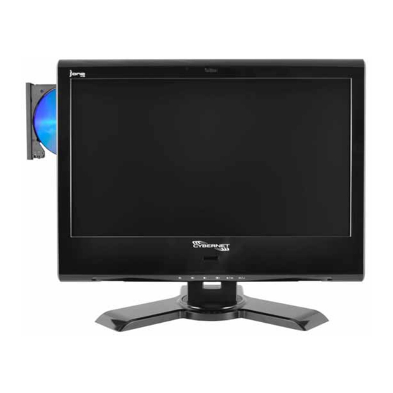
Figure 2: Left side view with Optical Drive Cybernet iOne-H6/H7 Page 4... -
Page 11: Figure 3: Power Button And Usb Ports
Figure 3: Power Button and USB Ports Figure 4: Touch Panel Figure 5: IrDA Receiver for TV Tuner Cybernet iOne-H6/H7 Page 5... -
Page 12: On Screen Display Buttons
Also functions as Exit button in the Menu Mode. Menu/Enter Press once to get to On-Screen display Mode to allow various adjustments as listed below. Also functions as the Enter or Select button in Menu Mode. Cybernet iOne-H6/H7 Page 6... -
Page 13: On Screen Display Usage
Screen Horizontal and Vertical adjustment, OSD display time set up Select to toggle through the languages offered. Select to reset all LCD Display settings OSD Firmware EEPROM version information Screen mode selection for 16:9 or 4:3 Cybernet iOne-H6/H7 Page 7... -
Page 14: Figure 8: Back View
Figure 8: Back view Figure 9: Bottom Panel I/O Ports Cybernet iOne-H6/H7 Page 8... -
Page 15: Figure 10: Cpu Heat Sink Ventilation Fan
Figure 10: CPU Heat Sink Ventilation Fan Figure 11: System Ventilation Fan, System Ventilation and Stand Cybernet iOne-H6/H7 Page 9... -
Page 17: System Assembly
Forceps/tweezers can be used to pick up tiny screws or set up the jumpers. Rubber gloves can prevent injury from static charge. Electric screwdriver can be used to secure all screws more quickly. Cybernet i-One H6/H7 System Assembly Page 10... -
Page 18: Orientation Of Key Parts
Orientation of Key Parts Figure 12: System Fans, CPU Heat Sink Fan and Ventilation Cybernet i-One H6/H7 System Assembly Page 11... -
Page 19: Ione-H6/H7 Disassembly
System FAN1 connector at bottom left corner next to the com port. And System Fan2 connector at bottom right corner next to the LVDS connector. Cybernet i-One H6/H7 System Assembly Page 12... -
Page 20: Figure 13: Open System
Figure 13: Open system without GPU Figure 14: Open system with GPU Cybernet i-One H6/H7 System Assembly Page 13... -
Page 21: Installing The Cpu
4. Close the cover and the lever to complete installation. Replace the heat sink. NOTE: Any violation of the correct installation procedures may cause permanent damage to your motherboard. Cybernet i-One H6/H7 System Assembly Page 14... -
Page 22: Installing The Cpu Heat Sink
3. Secure the two screws at the opposite end near the top edge of the bezel. 4. Connect the power cable to CPU Fan on the Motherboard labeled CPU FAN 1 connector. Cybernet i-One H6/H7 System Assembly Page 15... -
Page 23: Installing The Memory Module Ddr3 So-Dimm
3. Press the memory module down and the metal clip at each side of the DIMM slot will automatically close. 4. Repeat the steps to install another memory module to meet your needs. Cybernet i-One H6/H7 System Assembly Page 16... -
Page 24: Installing The Hard Disk Drive
Connect the SATA cable to the motherboard. SATA Cable 2. Connect the SATA cable, Connect the Power cable 3. Connect the other end of the SATA/Power cable to the Hard Disk Drive as shown. SATA/Power Cable Cybernet i-One H6/H7 System Assembly Page 17... -
Page 25: Installing The Optical Disk Drive
1. Remove back bezel as indicated in iOne Disassembly. Remove the Optical Disk Drive frame. 2. Put the ODD on the ODD frame and line up the four screw holes accordingly. 3. Secure the four screws on the ODD frame. Cybernet i-One H6/H7 System Assembly Page 18... - Page 26 5. Connect the other end of the cable to the ODD. 6. Install the ODD frame and line up the two screw holes over the Metal Support. 7. Secure the two screws to fix the ODD frame and complete the installation. Cybernet i-One H6/H7 System Assembly Page 19...
-
Page 27: Installing The Mini-Pcie Card (Optional)
Insert the mini-PCIe card at a 45° angle. Then, push it in until the golden fingers on the mini-PCIe card are deeply inserted in the mini-PCIe slots. 2. Press down the mini-PCIe card and secure with the small screws. Cybernet i-One H6/H7 System Assembly Page 20... -
Page 28: Installing The Cover
1. Connect the power cables from both the System Fans to the mainboard BEFORE securing the metal cover and I/O plate with 18 screws. 2. Secure the plastic cover with eight screws. 3. Secure the stand with four screws. Cybernet i-One H6/H7 System Assembly Page 21... - Page 29 System View Cybernet i-One H6/H7 System Assembly Page 22...
-
Page 30: Cybernet Recycling Sop
Cybernet e-recycling SOP Cybernet has an e-recycling program that is very easy to use. Just follow the steps explained below or go to our website at www.cybernetman.com. 1. Request an RMA via phone, email or support request. 2. We will arrange a call tag to have the product picked up. Just have it packed and ready to ship.
Need help?
Do you have a question about the H6 i-One Series and is the answer not in the manual?
Questions and answers