
Related Manuals for LSI ITI7004G2-


Summary of Contents for LSI ITI7004G2-
- Page 1 USER’S GUIDE 2 Gbit/s Fibre Channel to PCI Host Adapters Version 2.0 M a r c h 2 0 0 2 ® DB15-000182-01...
-
Page 2: Electromagnetic Compatibility Notices
Consult the dealer or an experienced radio/TV technician for help. LSI Logic is not responsible for any radio or television interference caused by unauthorized modification of this equipment or the substitution or attachment of connecting cables and equipment other than those specified by LSI Logic. - Page 3 LSI Logic Corporation. LSI Logic products are not intended for use in life-support appliances, devices, or systems. Use of any LSI Logic product in such applications without written consent of the appropriate LSI Logic officer is prohibited.
- Page 4 LSI Logic; nor does the purchase or use of a product from LSI Logic convey a license under any patent rights, copyrights, trademark rights, or any other of the intellectual property rights of LSI Logic or third parties.
- Page 5 Preface This book is the primary reference and user’s guide for the LSI Logic family of 2 Gbit/s Fibre Channel to PCI Host Adapter boards. It contains a complete functional description for each of these boards as well as complete physical and electrical specifications.
- Page 6 Chapter 2 for Link Activity and Link Fault LEDs, and addition of reference in Chapter 2 (and in the Preface) to Fusion-MPT Device Management User’s Guide. Preface Ver. 2.0 Copyright © 2002 by LSI Logic Corporation. All rights reserved.
-
Page 7: Table Of Contents
Electrical Characteristics Thermal, Atmospheric Characteristics Electromagnetic Compliance Safety Characteristics The PCI Interface The FC Interface The FC Link Activity/Link Fault LED LSI40919O Host Adapter Configuration LSI40919O Connector and Indicator LED Copyright © 2002 by LSI Logic Corporation. All rights reserved. - Page 8 ITI7004G2-LC Connector and Indicator LED Features Description Installing the FcUtil Program Link Speed Interrupt Coalescing Intel BIOS Features BIOS Overview Intel BIOS Boot Specification (BBS) Copyright © 2002 by LSI Logic Corporation. All rights reserved. 2-10 2-11 2-12 2-13 2-14 2-15 2-16 2-17...
- Page 9 Identifying the Fibre Channel Disks Verifying Correct Installation Adapter-Specific Settings Interrupt Coalescing Set Fibre Channel Link Speed Persistent Device Naming Manual Selection of Fibre Channel Topology Copyright © 2002 by LSI Logic Corporation. All rights reserved. 4-10 4-12 4-13 4-14 4-15 2-10...
- Page 10 ITI7004G2-LC Host Adapter Configuration 2.18 ITI7004G2-LC Connectors and Indicator LEDs Tables LSI Logic 2 Gbit/s Controllers and Associated Host Adapters 1-1 LSI Logic 2 Gbit/s FC Host Adapter Descriptions Hardware and Software Requirements Maximum Power Requirements Appearance of LED to Represent Link Status...
-
Page 11: Installing The 2 Gbit/S Host Adapters
Chapter 1 Installing the 2 Gbit/s Host Adapters This chapter contains general information about the LSI Logic family of 2 Gbit/s Fibre Channel (FC) to PCI host adapters. It also provides host adapter installation instructions and quick installation instructions for Windows NT or Windows 2000 device drivers. -
Page 12: Obtaining Windows Nt/Windows 2000 Drivers
Before you begin the 2 Gbit/s Fibre Channel to PCI host adapter installation, create a Windows NT or Windows 2000 driver diskette by copying the driver files from either the LSI Logic SDMS CD-ROM or from the LSI Logic web site at http://www.lsilogic.com. If you obtain the driver software from the LSI Logic web site, the zipped package that you download contains the appropriate files. -
Page 13: Detailed Installation Procedure
Before starting, look through the following task list to get an overall idea of the steps you will be performing. If you are not confident you can perform the tasks as described here, LSI Logic recommends getting assistance. Each FC host adapter channel that you install can act as host for up to 126 Arbitrated Loop FC devices, not including the adapter itself. - Page 14 64-bit PCI slot. If the host adapter is inserted in a 32-bit PCI slot, it will function as a 32-bit device. that is aligned with the PCI slot you intend to use. Save the bracket screw. Copyright © 2002 by LSI Logic Corporation. All rights reserved.
-
Page 15: Hardware Connections For The Lsi Logic Host Adapter
J2 should fit where you removed the blank panel. Detailed Installation Procedure Rev. 2.0 Copyright © 2002 by LSI Logic Corporation. All rights reserved. LSI Logic Host Adapter PCI Bus Edge Connector J1 Figure 1.1) of the host Figure 1.2. -
Page 16: Inserting The Host Adapter
Step 8. Secure the board with the bracket screw (see Figure 1.2) before making the external FC link connection. Step 9. Reconnect all power cords and boot your PC. Installing the 2 Gbit/s Host Adapters Rev. 2.0 Copyright © 2002 by LSI Logic Corporation. All rights reserved. -
Page 17: Gbit/S Host Adapter Characteristics
Section 2.6, “Physical Characteristics,” page 2-7 2.1 General Description The LSI Logic 2 Gbit/s Fibre Channel to PCI host adapter family uses state-of-the-art 2 Gbit/s Fibre Channel technology to provide the highest possible performance and most flexible storage configuration available. -
Page 18: Hardware And Software Support
ITI7004G2-LC 2 Gbit/s, Quad-port, Short-card, optical 2.1.1 Hardware and Software Support The LSI Logic 2 Gbit/s Fibre Channel to PCI host adapter family supports most major software operating systems, such as Sun Solaris (2.6 and greater), Windows Server (NT 4.0, 2000, XP, .NET), Linux (RedHat, Suse, Caldera, Turbo), NetWare, UnixWare, HP-UX, and OS/2. -
Page 19: Features
64-bit DMA bus master capable of 64-bit addressing. The LSIFC919 (single channel) and the LSIFC929 (dual channel) contain the PCI functionality for all the LSI Logic 2 Gbit/s Fibre Channel to PCI host adapters. The PCI interface includes these features:... -
Page 20: Fc Interface
Link fault LED 2.3 Physical Environment This section provides information about the physical, electrical, thermal, and safety characteristics of the LSI Logic 2 Gbit/s Fibre Channel to PCI host adapters. Additionally, these boards are compliant with electromagnetic standards set by the FCC. -
Page 21: Electrical Characteristics
2.3.1 Electrical Characteristics Table 2.3 lists the maximum power requirements, and includes all of the LSI Logic 2 Gbit/s Fibre Channel to PCI host adapter boards, under normal operation. Table 2.3 Host Adapter LSI44929O LSI44929LO LSI44929H LSI44929LH LSI40919O LSI40919LO LSI40919H... -
Page 22: Electromagnetic Compliance
PCI bus slot, all voltages are below the SELV 42.4 V limit. 2.4 Operational Environment Use the LSI Logic 2 Gbit/s Fibre Channel to PCI host adapter in PCI computer systems. The LSI Logic supplied FC BIOS and firmware operate the boards. An on-board flash memory device and a serial EEPROM are provided to allow BIOS code and open boot code support through PCI. -
Page 23: The Fc Interface
The LSI Logic 2 Gbit/s optical host adapter boards provide dual-purpose LEDs (one per port), visible through the bracket, which indicate activity on the FC link. Fault LED for the given link status for each of the LSI Logic optical host adapters. Table 2.4... -
Page 24: Lsi40919O Host Adapter Configuration
2.6.1 LSI40919O Host Adapter Configuration The LSI Logic LSI40919O is a single-channel 2 Gbit/s Fibre Channel adapter. One LC optical connector is used for I/O, which is accessible through the module bracket. The LSI40919O uses one LSIFC919 device, providing one Fusion-MPT channel. -
Page 25: Lsi40919O Connector And Indicator Led
Figure 2.2 Physical Characteristics Ver. 2.0 Link Activity/Link Fault LED - LSI40919O Link LSI40919O Connector and Indicator LED Channel 0 LED Channel 0 Copyright © 2002 by LSI Logic Corporation. All rights reserved. Figure 2.2. One Activity Fault Green Blinking Yellow... -
Page 26: Lsi40919Lo Host Adapter Configuration
2.6.3 LSI40919LO Host Adapter Configuration The LSI Logic LSI40919LO is a single-channel 2 Gbit/s Fibre Channel adapter. One LC optical connector is used for I/O, which is accessible through the module bracket. The LSI40919LO uses one LSIFC919 device, providing one Fusion-MPT channel. -
Page 27: Lsi40919Lo Connector And Indicator Led
Physical Characteristics Ver. 2.0 Link Activity/Link Fault LED - LSI40919LO Link LSI40919LO Connector and Indicator LED Channel 0 LED Channel 0 Copyright © 2002 by LSI Logic Corporation. All rights reserved. Figure 2.4. One Activity Fault Green Blinking Yellow 2-11... -
Page 28: Lsi40919H Host Adapter Configuration
2.6.5 LSI40919H Host Adapter Configuration The LSI Logic LSI40919H is a single-channel 2 Gbit/s Fibre Channel adapter. One HSSDC connector is used for I/O, which is accessible through the module bracket. The LSI40919H uses one LSIFC919 device, providing one Fusion-MPT channel. -
Page 29: Lsi40919H Connector
The LSI40919H I/O bracket is configured as shown in Figure 2.6. One HSSDC connector is used to connect the adapter channel to the Fibre Channel subsystem. Figure 2.6 LSI40919H Connector Channel 0 Physical Characteristics 2-13 Ver. 2.0 Copyright © 2002 by LSI Logic Corporation. All rights reserved. -
Page 30: Lsi40919Lh Host Adapter Configuration
2.6.7 LSI40919LH Host Adapter Configuration The LSI Logic LSI40919LH is a single-channel 2 Gbit/s Fibre Channel adapter. One HSSDC connector is used for I/O, which is accessible through the module bracket. The LSI40919LH uses one LSIFC919 device, providing one Fusion-MPT channel. -
Page 31: Lsi40919Lh Connector
The LSI40919LH I/O bracket is configured as shown in Figure 2.8. One HSSDC connector is used to connect the adapter channel to the Fibre Channel subsystem. Figure 2.8 LSI40919LH Connector Channel 0 Physical Characteristics 2-15 Ver. 2.0 Copyright © 2002 by LSI Logic Corporation. All rights reserved. -
Page 32: Lsi44929O Host Adapter Configuration
2.6.9 LSI44929O Host Adapter Configuration The LSI Logic LSI44929O is a dual-channel 2 Gbit/s Fibre Channel adapter. Two LC optical connectors are used for I/O, which are accessible through the module bracket. The LSI44929O uses one LSIFC929 device, providing two Fusion-MPT channels. -
Page 33: Lsi44929O Connector And Indicator Led
Physical Characteristics Ver. 2.0 Link Activity/Link Fault LED - LSI44929O Link Channel 1 LED Channel 1 Channel 0 LED Channel 0 Copyright © 2002 by LSI Logic Corporation. All rights reserved. Figure 2.10. Two Activity Fault Green Blinking Yellow 2-17... -
Page 34: Lsi44929Lo Host Adapter Configuration
2.6.11 LSI44929LO Host Adapter Configuration The LSI Logic LSI44929LO is a dual-channel 2 Gbit/s Fibre Channel adapter. Two LC optical connectors are used for I/O, which are accessible through the module bracket. The LSI44929LO uses one LSIFC929 device, providing two Fusion-MPT channels. -
Page 35: Lsi44929Lo Connector And Indicator Led
Physical Characteristics Ver. 2.0 Link Activity/Link Fault LED - LSI44929LO Link Channel 1 LED Channel 1 Channel 0 LED Channel 0 Copyright © 2002 by LSI Logic Corporation. All rights reserved. Figure 2.12. Two Activity Fault Green Blinking Yellow 2-19... -
Page 36: Lsi44929H Host Adapter Configuration
2.6.13 LSI44929H Host Adapter Configuration The LSI Logic LSI44929H is a dual-channel 2 Gbit/s Fibre Channel adapter. Two HSSDC connectors are used for I/O, which are accessible through the module bracket. The LSI44929H uses one LSIFC929 device, providing two Fusion-MPT channels. -
Page 37: Lsi44929H Connectors
HSSDC connectors are used to connect the adapter channel to the Fibre Channel subsystem. Figure 2.14 LSI44929H Connectors Physical Characteristics Ver. 2.0 Channel 1 Channel 0 Copyright © 2002 by LSI Logic Corporation. All rights reserved. Figure 2.14. Two 2-21... -
Page 38: Lsi44929Lh Host Adapter Configuration
2.6.15 LSI44929LH Host Adapter Configuration The LSI Logic LSI44929LH is a dual-channel 2 Gbit/s Fibre Channel adapter. Two HSSDC connectors are used for I/O, which are accessible through the module bracket. The LSI44929LH uses one LSIFC929 device, providing two Fusion-MPT channels. -
Page 39: Lsi44929Lh Connectors
HSSDC connectors are used to connect the adapter channel to the Fibre Channel subsystem. Figure 2.16 LSI44929LH Connectors Physical Characteristics Ver. 2.0 Channel 1 Channel 0 Copyright © 2002 by LSI Logic Corporation. All rights reserved. Figure 2.16. Two 2-23... -
Page 40: Iti7004G2-Lc Host Adapter Configuration
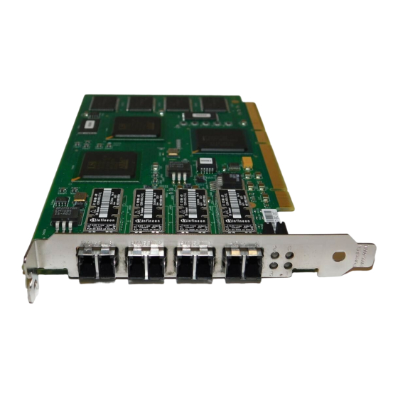
2.6.17 ITI7004G2-LC Host Adapter Configuration The LSI Logic ITI7004G2-LC is a quad-channel 2 Gbit/s Fibre Channel adapter. Four LC optical connectors are used for I/O, which are accessible through the module bracket. The ITI7004G2-LC uses two LSIFC929 devices, providing four Fusion-MPT channels. -
Page 41: Iti7004G2-Lc Connector And Indicator Led
2.6.18 ITI7004G2-LC Connector and Indicator LED The ITI7004G2-LC I/O bracket is configured as shown in Four LC connectors are used to connect the adapter channel to the Fibre Channel subsystem. The indicator LEDs are used to indicate link status, activity, and link fault for each channel. - Page 42 2-26 2 Gbit/s Host Adapter Characteristics Ver. 2.0 Copyright © 2002 by LSI Logic Corporation. All rights reserved.
-
Page 43: Firmware Installation Procedure
Section 3.4, “Configuring the Firmware,” page 3-4 Section 3.5, “Troubleshooting,” page 3-7 3.1 Introduction The LSI Logic Fibre Channel chips and host adapters contain firmware that presents a multi-protocol service layer based on the LSI Logic Fusion-MPT architecture. The Fibre Channel firmware provides FCP (SCSI-3 over Fibre Channel) Initiator, FCP Target, and LAN interface services to the host system. -
Page 44: Features
3.2.1 Features The Fibre Channel firmware for the LSI Logic Fibre Channel chips supports these features: 1 Gbit/s and 2 Gbit/s Fibre Channel transfers, with Auto Negotiation (user selects 1 Gbit/s, 2 Gbit/s, or Auto) 32-bit and 64-bit PCI support 33 MHz and 66 MHz PCI support Transaction performance capability of >70,000 I/Os per second (both... -
Page 45: Installing The Firmware
Fibre Channel unique exceptions. With the Fusion-MPT architecture, parallel SCSI host drivers can be used with the LSI Logic Fibre Channel controllers with little or no additional functionality for Fibre Channel. -
Page 46: Configuring The Firmware
If for some reason this automatic operation fails (e.g., other nodes on a loop not supporting Auto Negotiation), the LSI Logic host adapters may be configured to either the 2 Gbit/s or 1 Gbit/s speed, specifically. -
Page 47: Interrupt Coalescing
These values may be used to tune host adapter performance within a system environment. Note that the LSI44929 has two FC ports (the ITI7004G2-LC has four), so Interrupt Coalescing must be configured for each port. The LSI40919 has only one port. - Page 48 0x9. This default value is optimized for very high performance servers and peripherals. The user can decrease this value to improve system performance, if the system contains lower performance servers and/or peripherals. Copyright © 2002 by LSI Logic Corporation. All rights reserved.
-
Page 49: Troubleshooting
Host Adapter boards. When these errors occur, the LED flashes a four-digit sequence, which is the error code. These types of errors should be reported to LSI Logic Technical Support. The technical support person will ask for additional system configuration information, including the type of system used, the FC configuration and type of peripherals (including version numbers),... - Page 50 Firmware Installation Procedure Ver. 2.0 Copyright © 2002 by LSI Logic Corporation. All rights reserved.
-
Page 51: Bios Features
firmware. The LSI Logic BIOS integrates with a standard system BIOS, extending the standard disk service routine provided through INT13h. Two types of BIOS are available for the LSI Logic host adapters: An Intel BIOS for Intel-based platforms, and Open Boot BIOS for Solaris SPARC platforms. -
Page 52: Intel Bios
Boot Connection Devices menu appears with a list of available boot options. Use that menu to select the device and rearrange the order. Then exit to continue the boot process. BIOS Features Ver. 2.0 Copyright © 2002 by LSI Logic Corporation. All rights reserved. -
Page 53: Starting The Intel Bios Configuration Utility
4.3 Starting the Intel BIOS Configuration Utility The LSI Logic Intel BIOS allows you to change the default configuration of your host adapters, using the embedded BIOS Configuration Utility. When the BIOS loads, the following message appears on your monitor: Press Ctrl-C to start LSI Logic Configuration Utility... -
Page 54: Adapter Properties Menu
Global Properties allows changes to global scope settings. Refer to Section 4.5.5, “Global Properties Menu,” page 4-6, information. Only adapters with LSI Logic Control enabled can be accessed. 4.5.1 Adapter Properties Menu The Adapter Properties menu allows you to view and modify adapter settings. -
Page 55: Device Properties Menu
The Boot Adapter List menu specifies the order in which adapters boot when more than one LSI Logic host adapter is in a system. Up to four adapters in a system can be selected as bootable. Only one of the four bootable adapters can be used to control a Boot Volume. -
Page 56: Global Properties Menu
Utility Important: 4.7 Troubleshooting The LSI Logic Intel BIOS Configuration Utility is a powerful tool. If, while using it, you somehow disable all of your controllers, pressing Ctrl-A or Ctrl-E after memory initialization during reboot allows you to re-enable and reconfigure. -
Page 57: Open Boot Bios
Solaris Sparc 2.6, 2.7, and Solaris 8 Open Firmware environments Root Boot device selection from any target device Standard command line interface, with help query Configuration options and selection for each host adapter Open Boot BIOS Ver. 2.0 Copyright © 2002 by LSI Logic Corporation. All rights reserved. -
Page 58: Identifying The Fibre Channel Disks
WWN 210000203710324a Port ID 73 /pci@8,700000/scsi@6 BIOS Features Ver. 2.0 Disk DDRS-34560D Disk SEAGATE ST39173FC Disk SEAGATE ST39173FC Disk SEAGATE ST39173FC Disk SEAGATE ST39173FC Disk SEAGATE ST39173FC Copyright © 2002 by LSI Logic Corporation. All rights reserved. DC1B 6615 6258 6258 6258 6258... -
Page 59: Verifying Correct Installation
Target 6 Unit 0 Removable Read Only device PLEXTOR CD-ROM PX-20TS If the Fibre Channel devices on your LSI Logic/IntraServer adapter are not identified by your system, check the following: Is the Fibre Channel enclosure powered ON? Does the LED on the adapter indicate LINK? (Note that LINK is valid only after the device is probed.) -
Page 60: Adapter-Specific Settings
/pci@8,700000/IntraServer,fc@1 identifies the first Fibre Channel interface on an LSI Logic LSIFC929- based adapter. /pci@8,700000/IntraServer,fc@1,1 identifies the second Fibre Channel interface on an LSI Logic LSIFC929-based adapter. An LSI Logic LSIFC919-based adapter will show only one such Fibre Channel device. - Page 61 03001014 00000000 00000000 00000000 00020000 0300101c 00000000 00000000 00000000 00010000 02001030 00000000 00000000 00000000 00100000 1.00.16 scsi-2 IntraServer,fc 00000000 00000001 00010000 00000001 00000040 00000010 00000008 0000001e 00000621 000013e9 00000001 00000621 00001000 Copyright © 2002 by LSI Logic Corporation. All rights reserved. 4-11...
-
Page 62: Interrupt Coalescing
I/Os are coming into the adapter rapidly—for example, when performing small sequential reads from a disk. LSI Logic has performed significant testing under multiple I/O conditions, and has determined that the interrupt coalescence values that are beneficial over a wide range of I/O conditions are a depth of 9, with a... -
Page 63: Set Fibre Channel Link Speed
9 I/Os processed by the chip, unless 1280 microseconds has passed since the host was last interrupted. Although LSI Logic has determined that these settings are optimal for a wide variety of situations, your own I/O load may benefit from a deeper queue, or a longer timeout. -
Page 64: Persistent Device Naming
BIOS Features Ver. 2.0 <- command with no arguments prints help The system must be power cycled before the changes take effect. It is not sufficient to execute the reset-all command. Copyright © 2002 by LSI Logic Corporation. All rights reserved. -
Page 65: Manual Selection Of Fibre Channel Topology
Fibre Channel adapter. This can be done on a port by port basis, by using the following procedure. Note that it should not be necessary to Open Boot BIOS Ver. 2.0 Disk SEAGATE ST39173FC <- command with no arguments prints help Copyright © 2002 by LSI Logic Corporation. All rights reserved. 6615 4-15... - Page 66 = a ok 1 set-topology Topology selected is NL_Port Topology has been set Change will take effect after system power cycle 4-16 BIOS Features Ver. 2.0 NL_Port N_Port auto Copyright © 2002 by LSI Logic Corporation. All rights reserved.
- Page 67 Change will take effect after system power cycle Note: The system must be power cycled before the changes take effect. It is not sufficient to execute the reset-all command. Open Boot BIOS Ver. 2.0 Copyright © 2002 by LSI Logic Corporation. All rights reserved. 4-17...
- Page 68 4-18 BIOS Features Ver. 2.0 Copyright © 2002 by LSI Logic Corporation. All rights reserved.
-
Page 69: Appendix A Glossary Of Terms And Abbreviations
A unit of information consisting of eight bits. Channel A point-to-point link, the main task of which is to transport data from one point to another. 2 Gbit/s Fibre Channel to PCI Host Adapters Ver. 2.0 Copyright © 2002 by LSI Logic Corporation. All rights reserved. - Page 70 FC Physical standard, consisting of the three lower levels; FC-0, FC-1, and FC-2. FC-0 Lowest level of the FC Physical standard, covering the physical characteristics of the interface and media. Glossary of Terms and Abbreviations Ver. 2.0 Copyright © 2002 by LSI Logic Corporation. All rights reserved.
- Page 71 Hard Disk A disk made of metal and permanently sealed into a drive cartridge. A hard disk can store very large amounts of information. Glossary of Terms and Abbreviations Ver. 2.0 Copyright © 2002 by LSI Logic Corporation. All rights reserved.
- Page 72 Refers to delivering a single transmission to multiple destination N_Ports. Network Interface Card. N_Port “Node” port, a FC defined hardware entity at the node end of a link. Glossary of Terms and Abbreviations Ver. 2.0 Copyright © 2002 by LSI Logic Corporation. All rights reserved.
- Page 73 See Port Address. Random Access Memory. The computer’s primary working memory in which program instructions and data are stored and are accessible to the Glossary of Terms and Abbreviations Ver. 2.0 Copyright © 2002 by LSI Logic Corporation. All rights reserved.
- Page 74 One of the ways data is transferred over the SCSI bus. Transfers are Data Transfer clocked with fixed frequency pulses. This is faster than asynchronous Glossary of Terms and Abbreviations Ver. 2.0 Copyright © 2002 by LSI Logic Corporation. All rights reserved.
- Page 75 A technical committee of the Accredited Standards Committee X3, titled X3T9 I/O Interfaces. It is tasked with developing standards for moving data in and out of central computers. Glossary of Terms and Abbreviations Ver. 2.0 Copyright © 2002 by LSI Logic Corporation. All rights reserved.
- Page 76 Glossary of Terms and Abbreviations Ver. 2.0 Copyright © 2002 by LSI Logic Corporation. All rights reserved.
-
Page 77: Customer Feedback
Thank you for your help in improving the quality of our documents. 2 Gbit/s Fibre Channel to PCI Host Adapters Ver. 2.0 Copyright © 2002 by LSI Logic Corporation. All rights reserved. - Page 78 Fax: 408.433.4333 Excellent Good Average ____ ____ ____ ____ ____ ____ ____ ____ ____ ____ ____ ____ Copyright © 2002 by LSI Logic Corporation. All rights reserved. Fair Poor ____ ____ ____ ____ ____ ____ ____ ____ ____ ____ ____...
- Page 80 You can find a current list of our U.S. distributors, international distributors, and sales offices and design resource centers on our web site at http://www.lsilogic.com/contacts/na_salesoffices.html...
Need help?
Do you have a question about the ITI7004G2- and is the answer not in the manual?
Questions and answers