Table of Contents
Advertisement
MODEL
PM-12-45
w/CFB and TCS
Table Of Contents
Topic
Regulation
D.C. Fuses
Gel/Lead Acid Selector
M-PMSER-PM1245
As of January 2011
1
P.O. Box 1306, Newport Beach, California 92663 • Phone: 714-751-0488 • Fax: 714-957-1621 • E-Mail: techservice@newmarpower.com
PM Series Power Module
Power Supply/Battery Charger
INSTALLATION / OPERATION MANUAL
www.newmartelecom.com
Page
2
3
3
3
3
3
4
4
4
5
6
6
7
7
7
7
8
8
8
8
9
9
9
10
Advertisement
Table of Contents

Related Manuals for NewMar PM-12-40


Summary of Contents for NewMar PM-12-40
-
Page 1: Table Of Contents
PM Series Power Module Power Supply/Battery Charger INSTALLATION / OPERATION MANUAL MODEL PM-12-45 w/CFB and TCS Table Of Contents Topic Page QUICK REFERENCE CONTENTS I) OVERVIEW II) AC POWER QUALITY AND EMI COMPATIBILITY B) EMI (Electro-magnetic Interference) C) Other Factors III) INSTALLATION A) Materials Provided B) Mounting... -
Page 2: Quick Reference Contents
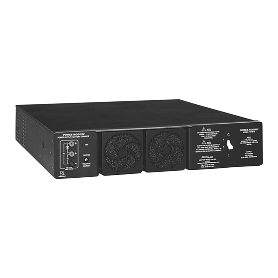
Quick Reference Contents The front and rear panel features of the Power Modules are illustrated below, along with the page number where information on each particular feature is located. FIGURE 1: Power Module Front Panel (all models): PM "ON' Cooling Fans, Input Switch/ Indicator LED, Page 7... -
Page 3: I) Overview
In some as part of an integrated system with the PFM-400 refer to the manual cases linear power supplies (also available from NEWMAR) should be which comes with that unit for all d.c. wiring instructions and functional considered, as they emit lower EMI (although they are more susceptible to “brown-outs”... -
Page 4: A) Materials Provided
A) Materials Provided input select switch located on the left hand side of the PM into the proper position. Positions are identified on the switch. Use a small screwdriver to slide the switch into position. No adjustment is necessary for either 50 or Prior to installation, check to ensure that each of the following items have 60 Hz input. -
Page 5: D) Dc Output Wiring
Model Minimum Wire Size per N.E.C. AWG (mm) PM-48-10 #16 (2 mm) PM-24-20, PM-48-18 #14 (2.5 mm) (-) Negative to Load PM-12-40, PM-12-45, PM-24-35 #8 (10 mm) BATTERY or Distribution Panel PM-12-70 #6 (16 mm) To minimize line loss at lengths greater than 5 feet, it is recommended to increase wire size one gauge for each additional 5 feet of cable run. -
Page 6: E) Parallel Wiring
E) Parallel Wiring FIGURE 9: Parallel (two to six Power Modules) and N+1 redundancy, negative ground The internal oring/isolation diode of the PM allows parallel n+1 redundant wiring with no modification or other external isolation de vices required. Figures 9-10 on the following page illustrate some typical parallel wiring schemes. -
Page 7: Iv) Operation
The PM is rated for continuous duty at the current mating board connector. level indicated by model number, e.g., PM-12-40 is rated at 40 amps con- 5. When installing replacement fan: tinuous duty. To prevent overload when recharging severely discharged A. -
Page 8: D) Remote Shutdown
D) Remote Shutdown A color-coded wire “pigtail” with keyed plug is provided for wiring convenience and to assure proper connections. The plug holds three wires for the output fail relay. Remote shutdown of the PM via TTL signal is an option that can be wired in at the time of installation. -
Page 9: Three Stage Charging
† For parallel configuration/load sharing derate output 10% * With three-stage charger function board installed; for parallel charging A DC wiring harness quick connect kit is available from NEWMAR which multiply A/H capacity by number of units simplifies parallel wiring installation of multiple Power Modules with the Power Function Manager and facilitates “hot change-out”... -
Page 10: Vii) Troubleshooting
4. Replace blown fuse (See section IV-B, DC Output.) 5. Return to place of purchase for repair/re- placement or contact NEWMAR for return authorization. B. PM repeatedly trips input circuit 1. AC input select switch set to 115V (560 watt 1.
Need help?
Do you have a question about the PM-12-40 and is the answer not in the manual?
Questions and answers