Table of Contents
Advertisement
Quick Links
Installation/Operation Manual
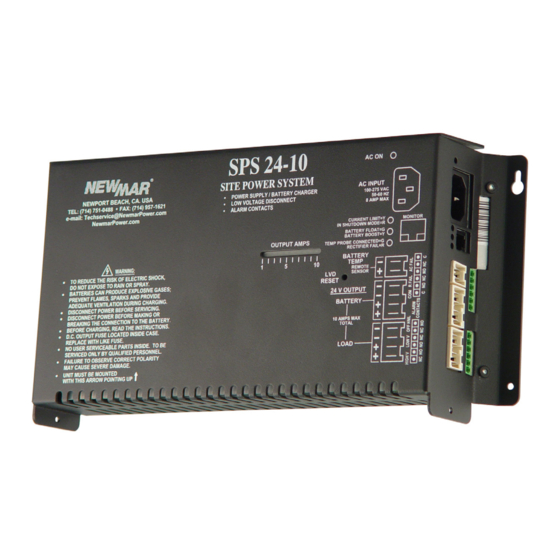
Models: SPS 12-20, SPS 24-10, SPS 48-6
Table of Contents
P.O. Box 1306
Newport Beach
California 92663
Site Power System
Page Table of Contents
2
2
2
2
2
3
3
3
4
4
4
4
4
4
4
4
5
5
5
5
6
7
4.9
E-Mail: techservice@newmarpower.com
Page
7
7
8
8
9
9
9
9
10
10
10
11
11
11
12
12
12
12
12
13
13
13
14
Manual-SPS
As of May 2012
Phone: 714-751-0488
Fax: 714-957-1621
Advertisement
Table of Contents


Need help?
Do you have a question about the SPS 12-20 and is the answer not in the manual?
Questions and answers