
Subscribe to Our Youtube Channel
Related Manuals for EWM Picotig 200 puls TG


Summary of Contents for EWM Picotig 200 puls TG
- Page 1 Operating instructions Welding machine Picotig 200 puls TG 099-002058-EW501 Observe additional system documents! 26.11.2020...
- Page 2 +49 2680 181-0. A list of authorised sales partners can be found at www.ewm-group.com/en/specialist-dealers. Liability relating to the operation of this equipment is restricted solely to the function of the equipment. No other form of liability, regardless of type, shall be accepted.
-
Page 3: Table Of Contents
Contents Notes on using these operating instructions Contents 1 Contents ............................3 2 For your safety ..........................5 Notes on using these operating instructions ................5 Explanation of icons ....................... 6 Safety instructions ........................7 Transport and installation ....................10 3 Intended use .......................... - Page 4 Contents Notes on using these operating instructions 5.3.1 Connecting the electrode holder and workpiece lead .......... 35 5.3.2 Welding task selection ..................35 5.3.3 Hotstart ......................... 36 5.3.4 Arcforce......................... 36 5.3.5 Antistick......................... 36 5.3.6 Average value pulse welding ................36 5.3.7 Expert menu (MMA) ....................
-
Page 5: For Your Safety
For your safety Notes on using these operating instructions For your safety Notes on using these operating instructions DANGER Working or operating procedures which must be closely observed to prevent imminent serious and even fatal injuries. • Safety notes include the "DANGER" keyword in the heading with a general warning symbol. •... -
Page 6: Explanation Of Icons
For your safety Explanation of icons Explanation of icons Symbol Description Symbol Description Indicates technical aspects which the u- Activate and release / Tap / Tip ser must observe. Switch off machine Release Switch on machine Press and hold Switch Incorrect / Invalid Turn Correct / Valid... -
Page 7: Safety Instructions
For your safety Safety instructions Safety instructions WARNING Risk of accidents due to non-compliance with the safety instructions! Non-compliance with the safety instructions can be fatal! • Carefully read the safety instructions in this manual! • Observe the accident prevention regulations and any regional regulations! •... - Page 8 For your safety Safety instructions WARNING Risk of injury due to radiation or heat! Arc radiation can lead to skin and eye injuries. Contact with hot workpieces and sparks can lead to burns. • Use hand shield or welding helmet with the appropriate safety level (depends on the appli- cation).
- Page 9 For your safety Safety instructions CAUTION Smoke and gases! Smoke and gases can lead to breathing difficulties and poisoning. In addition, solvent vapour (chlorinated hydrocarbon) may be converted into poisonous phosgene due to the ultraviolet radiation of the arc! • Ensure that there is sufficient fresh air! •...
-
Page 10: Transport And Installation
For your safety Transport and installation CAUTION Obligations of the operator! The respective national directives and laws must be complied with when operating the machine! • Implementation of national legislation relating to framework directive 89/391/EEC on the int- roduction of measures to encourage improvements in the safety and health of workers at work and associated individual guidelines. - Page 11 For your safety Transport and installation CAUTION Risk of accidents due to supply lines! During transport, attached supply lines (mains leads, control cables, etc.) can cause risks, e.g. by causing connected machines to tip over and injure persons! • Disconnect all supply lines before transport! Risk of tipping! There is a risk of the machine tipping over and injuring persons or being damaged itself during movement and set up.
-
Page 12: Intended Use
3.3.1 Warranty For more information refer to the "Warranty registration" brochure supplied and our information regarding warranty, maintenance and testing at www.ewm-group.com! 3.3.2 Declaration of Conformity This product corresponds in its design and construction to the EU directives listed in the decla- ration. -
Page 13: Part Of The Complete Documentation
Intended use Documents which also apply 3.3.6 Part of the complete documentation This document is part of the complete documentation and valid only in combination with all other parts of these instructions! Read and observe the operating instructions for all system components, especially the safety instructions! The illustration shows a general example of a welding system. -
Page 14: Machine Description - Quick Overview
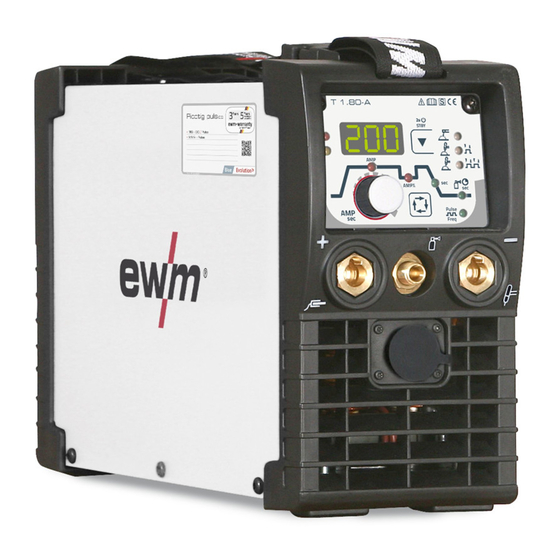
Machine description – quick overview Front view Machine description – quick overview Front view Figure 4-1 Item Symbol Description Carrying strap > see 5.1.4.1 chapter Machine control > see 4.3 chapter Connection socket, “+” welding current How to connect the accessories depends on the welding procedure. Please observe the connection description for the corresponding welding procedure >... -
Page 15: Rear View
Machine description – quick overview Rear view Rear view Figure 4-2 Item Symbol Description Main Switch Switching the machine on or off. Cooling air inlet Mains connection cable > see 5.1.7 chapter Connection thread - G¼" Shielding gas connection (inlet) Connection socket, 19-pole Remote control connection 099-002058-EW501... -
Page 16: Machine Control - Operating Elements
Machine description – quick overview Machine control – Operating elements Machine control – Operating elements The parameters and their setting ranges are described in chapter Parameters Overview - Setting Ran- ges > see 10.1 chapter. Figure 4-3 Item Symbol Description AMP% Secondary current (TIG) -
Page 17: Welding Data Display
Machine description – quick overview Machine control – Operating elements 4.3.1 Welding data display The machine will be calibrated for approx. 2 seconds each time it is switched on. This will be indicated by on the display. Subsequently, the value set for the dynamic power adjustment will be displayed for approx. -
Page 18: Design And Function
Design and function Transport and installation Design and function WARNING Risk of injury from electrical voltage! Contact with live parts, e.g. power connections, can be fatal! • Observe the safety information on the first pages of the operating instructions! • Commissioning must be carried out by persons who are specifically trained in handling power sources! •... -
Page 19: Ambient Conditions
Design and function Transport and installation 5.1.3 Ambient conditions T he machine must not be operated in the open air and must only be set up and operated on a suitable, stable and level base! • The operator must ensure that the ground is non-slip and level, and provide sufficient lighting for the place of work. -
Page 20: Notes On The Installation Of Welding Current Leads
Design and function Transport and installation 5.1.5 Notes on the installation of welding current leads • Use an individual welding lead to the workpiece for each welding machine! Figure 5-2 • Fully unroll welding current leads, torch hose packages and intermediate hose packages. Avoid loops! •... -
Page 21: Stray Welding Currents
Design and function Transport and installation 5.1.6 Stray welding currents WARNING Risk of injury due to stray welding currents! Stray welding currents can destroy protective earth conductors, damage machines and electronic devices and cause overheating of components, leading to fire. •... -
Page 22: Mains Connection
Design and function Transport and installation 5.1.7 Mains connection DANGER Hazards caused by improper mains connection! An improper mains connection can cause injuries or damage property! • The connection (mains plug or cable), the repair or voltage adjustment of the device must be carried out by a qualified electrician in accordance with the respective local laws or nati- onal regulations! •... -
Page 23: Tig Welding
Design and function TIG welding TIG welding 5.2.1 Welding torch and workpiece line connection Prepare welding torch according to the welding task in hand (see operating instructions for the torch). Figure 5-6 Item Symbol Description Welding torch Welding torch hose package Connection socket, "-"... -
Page 24: Shielding Gas Supply (Shielding Gas Cylinder For Welding Machine)
Design and function TIG welding 5.2.2 Shielding gas supply (shielding gas cylinder for welding machine) WARNING Risk of injury due to improper handling of shielding gas cylinders! Improper handling and insufficient securing of shielding gas cylinders can cause seri- ous injuries! •... -
Page 25: Shielding Gas Hose Connection
Design and function TIG welding 5.2.2.2 Shielding gas hose connection Figure 5-9 Item Symbol Description Connection thread - G¼" Shielding gas connection (inlet) • Screw the gas hose connection nipple onto the G¼" connection nipple. 5.2.2.3 Gas test – setting the shielding gas volume CAUTION Electric shocks! When setting the shielding gas quantity, high voltage ignition pulses or open circuit vol-... -
Page 26: Arc Ignition
Design and function TIG welding 5.2.3 Arc ignition To change the ignition type, use parameter to switch between HF start ( ) and lift arc ( ) in the Expert menu > see 5.2.8 chapter. 5.2.3.1 HF ignition Figure 5-10 The arc is started without contact from high-voltage ignition pulses. -
Page 27: Welding Task Selection
Design and function TIG welding 5.2.4 Welding task selection Figure 5-12 This completes the basic settings and you can now start welding. Further welding parameters, such as gas pre-flow time, are predefined for the most common applications but can be adjusted when necessary > see 5.2.8 chapter. 5.2.5 Operating modes (functional sequences) Using the welding parameter push-button and welding parameter setting rotary knob the sequence para-... -
Page 28: Tig Non-Latched Operation
Design and function TIG welding 5.2.5.2 TIG non-latched operation When the foot-operated remote control is connected, the machine switches automatically to non-latched operation. The up- and down-slopes are switched off. Figure 5-13 cycle: • Press and hold torch trigger 1. •... -
Page 29: Tig Latched Operation
Design and function TIG welding 5.2.5.3 TIG latched operation Figure 5-14 cycle • Press torch trigger 1 , the gas pre-flow time elapses. • HF start pulses jump from the electrode to the workpiece. The arc ignites. • Welding current flows and immediately assumes the set ignition current (search arc at minimum setting). -
Page 30: Welding Torch (Operating Variants)
Design and function TIG welding 5.2.6 Welding torch (operating variants) Different torch versions can be used with this machine. Functions on the operating elements, such as torch triggers (BRT), rockers or potentiometers, can be mo- dified individually via torch modes. Explanation of symbols for operating elements: Symbol Description... - Page 31 Design and function TIG welding Standard torch with two torch triggers Figure Operating ele- Explanation of symbols ments BRT1 = torch trigger 1 BRT2 = torch trigger 2 Functions Mode Operating ele- ments Welding current on/off Secondary current (ex works) Secondary current (tapping function) )/(latched operating mode) Welding current on/off...
- Page 32 Design and function TIG welding Standard torch with one rocker (rocker, two torch triggers) Figure Operating ele- Explanation of symbols ments BRT 1 = torch trigger 1 BRT 2 = torch trigger 2 Functions Mode Operating ele- ments Welding current on/off Secondary current (ex works) Secondary current (tapping function)
-
Page 33: Average Value Pulse Welding
Design and function TIG welding 5.2.7 Average value pulse welding Average value pulse welding means that two currents are switched periodically, a current average value (AMP), a pulse current (Ipuls), a balance ( ) and a frequency ( ) having been defined first. The predefined ampere current average value is decisive, the pulse current (Ipuls) is defined by the para- meter as a percentage of the current average value (AMP). -
Page 34: Expert Menu (Tig)
Design and function TIG welding 5.2.8 Expert menu (TIG) Figure 5-17 Display Setting/selection Switch ignition mode HF ignition Liftarc Gas pre-flow time Ignition current (as percentage, dependent on main current) Upslope time to main current End-crater current Setting range in percent: depending on main current Setting range, absolute: Imin to Imax. -
Page 35: Mma Welding
Design and function MMA welding MMA welding 5.3.1 Connecting the electrode holder and workpiece lead CAUTION Risk of crushing and burns! When changing stick electrodes there is a risk of crushing and burns! • Wear appropriate and dry protective gloves. •... -
Page 36: Hotstart
Design and function MMA welding 5.3.3 Hotstart The function hot start ensures a secure igniting of the arc and a sufficient heating to the still cold parent metal at the beginning of the welding process. The ignition takes place here with increased current (hot start current) over a certain time (hot start time). -
Page 37: Expert Menu (Mma)
Design and function MMA welding Figure 5-23 Display Setting/selection Pulse welding (average value pulses) ------ Function switched on ------ Function switched off (ex works) Pulse frequency More parameters can be set in the Expert menu > see 5.3.7 chapter. 5.3.7 Expert menu (MMA) Figure 5-24 Display... -
Page 38: Remote Control
Design and function Remote control Display Setting/selection Arcforce correction • Increase value > harder arc • Decrease value > softer arc Pulse balance Pulse current > see 5.3.6 chapter Remote control The remote controls are operated on the 19-pole remote control connection socket (analogue). 5.4.1 RTF1 19POL Functions... -
Page 39: Machine Configuration Menu
Design and function Machine configuration menu Machine configuration menu Figure 5-25 Display Setting/selection Calibration The machine will be calibrated for approx 2 seconds each time it is switched on. Exit the menu Exit Torch configuration menu Set welding torch functions Torch mode (ex works 1) >... - Page 40 Design and function Machine configuration menu Display Setting/selection Re-ignition after arc interruption > see 5.2.3.3 chapter ------- Function switched off or time setting Arc detection for welding helmets (TIG) Modulated waviness for better arc detection ------- Function enabled ------ Function disabled Service menu Any changes to the service menu should be agreed with the authorised service person- nel.
-
Page 41: Maintenance, Care And Disposal
Maintenance, care and disposal General Maintenance, care and disposal General DANGER Risk of injury due to electrical voltage after switching off! Working on an open machine can lead to fatal injuries! Capacitors are loaded with electrical voltage during operation. Voltage remains present for up to four minutes after the mains plug is removed. -
Page 42: Maintenance Work, Intervals
A periodic test according to IEC 60974-4 "Periodic inspection and test" has to be carried out. In addition to the regulations on testing given here, the relevant local laws and regulations must also be observed. For more information refer to the "Warranty registration" brochure supplied and our information regarding warranty, maintenance and testing at www.ewm-group.com! 099-002058-EW501 26.11.2020... -
Page 43: Disposing Of Equipment
• Information about returning used equipment or about collections can be obtained from the respective municipal administration office. • In addition to this, returns are also possible throughout Europe via EWM sales partners. 099-002058-EW501 26.11.2020... -
Page 44: Rectifying Faults
Rectifying faults Checklist for rectifying faults Rectifying faults All products are subject to rigorous production checks and final checks. If, despite this, something fails to work at any time, please check the product using the following flowchart. If none of the fault rectification procedures described leads to the correct functioning of the product, please inform your authorised dea- ler. -
Page 45: Error Messages (Power Source)
Rectifying faults Error messages (power source) Unstable arc Material inclusions in the tungsten electrode due to contact with filler material or workpiece Regrind or replace the tungsten electrode Incompatible parameter settings Check settings and correct if necessary ... - Page 46 Rectifying faults Error messages (power source) Error message Possible cause Remedy Start signal set in the event of er- Do not press the torch trigger or the foot-opera- rors ted remote control Temperature error Allow the machine to cool down Mains overvoltage Switch off the machine and check the mains vol- tage...
-
Page 47: Resetting Welding Parameters To The Factory Settings
Rectifying faults Resetting welding parameters to the factory settings Resetting welding parameters to the factory settings All customised welding parameters that are stored will be replaced by the factory settings. Figure 7-1 Display Setting/selection Calibration The machine will be calibrated for approx 2 seconds each time it is switched on. Initialising Keep the push-button pressed until is shown on the display. -
Page 48: Technical Data
Technical data Picotig 200 Technical data Performance specifications and guarantee only in connection with original spare and replacement parts! Picotig 200 Welding current (I 5 A to 200 A 5 A to 150 A Welding voltage according to standard (U 10,2 V to 18,0 V 20,2 V to 26,0 V Duty cycle DC at 40°... -
Page 49: Accessories
Accessories Transport system Accessories Performance-dependent accessories like torches, workpiece leads, electrode holders or intermediate hose packages are available from your authorised dealer. Transport system Type Designation Item no. Trolly 35-1 Transport vehicle 090-008629-00000 Options Type Designation Item no. ON Filter T.0003 Dirt filter for air inlet 092-002546-00000 ON Safeguard T.0003... -
Page 50: Appendix
Appendix Parameter overview – setting ranges Appendix 10.1 Parameter overview – setting ranges 10.1.1 TIG welding Parameters/function Setting range Secondary current AMP% Down-slope time Gas post-flow time Pulse welding Pulse frequency - 2000 HF start Gas pre-flow time Ignition current Up-slope time 20,0 End-crater current AMP%... -
Page 51: Basic Parameters (Independent Of Process)
Appendix Parameter overview – setting ranges 10.1.3 Basic parameters (independent of process) Parameters/function Setting range Switched on Switched off Calibration Initialisation Machine configuration Exit menu Torch configuration Torch mode Up/down speed Service menu Software version of the machine control Dynamic power adjustment (10 A, 16 A, 20 A) Time-based power-saving mode min. -
Page 52: Searching For A Dealer
Appendix Searching for a dealer 10.2 Searching for a dealer Sales & service partners www.ewm-group.com/en/specialist-dealers "More than 400 EWM sales partners worldwide" 099-002058-EW501 26.11.2020...
Need help?
Do you have a question about the Picotig 200 puls TG and is the answer not in the manual?
Questions and answers