
Subscribe to Our Youtube Channel
Related Manuals for EWM Picotig 200 TG


Summary of Contents for EWM Picotig 200 TG
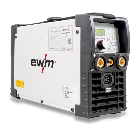
- Page 1 Operating instructions Welding machine Picotig 200 TG 099-002058-EW501 26.11.2015 Register now and benefit! Jetzt Registrieren und Profitieren! www.ewm-group.com...
-
Page 2: General Instructions
+49 2680 181-0. A list of authorised sales partners can be found at www.ewm-group.com. Liability relating to the operation of this equipment is restricted solely to the function of the equipment. -
Page 3: Table Of Contents
Contents Notes on the use of these operating instructions Contents 1 Contents ..............................3 2 Safety instructions ..........................5 Notes on the use of these operating instructions ................5 Explanation of icons ........................6 General ............................7 Transport and installation ......................11 2.4.1 Ambient conditions ....................... - Page 4 8 Technical data............................51 Picotig 200 ........................... 51 9 Accessories ............................52 Transport systems ........................52 Options ............................52 Remote controls and accessories ....................52 General accessories ........................52 10 Appendix A ............................53 10.1 Overview of EWM branches......................53 099-002058-EW501 26.11.2015...
-
Page 5: Safety Instructions
Safety instructions Notes on the use of these operating instructions Safety instructions Notes on the use of these operating instructions DANGER Working or operating procedures which must be closely observed to prevent imminent serious and even fatal injuries. • Safety notes include the "DANGER" keyword in the heading with a general warning symbol. •... -
Page 6: Explanation Of Icons
Safety instructions Explanation of icons Explanation of icons Symbol Description Special technical points which users must observe. Correct Wrong Press Do not press Press and keep pressed Turn Switch Switch off machine Switch on machine enter the menu ENTER Navigating in the menu NAVIGATION Exit the menu EXIT... -
Page 7: General
Safety instructions General General DANGER Electromagnetic fields! The power source may cause electrical or electromagnetic fields to be produced which could affect the correct functioning of electronic equipment such as IT or CNC devices, telecommunication lines, power cables, signal lines and pacemakers. •... - Page 8 Safety instructions General WARNING Smoke and gases! Smoke and gases can lead to breathing difficulties and poisoning. In addition, solvent vapour (chlorinated hydrocarbon) may be converted into poisonous phosgene due to the ultraviolet radiation of the arc! • Ensure that there is sufficient fresh air! •...
- Page 9 Safety instructions General CAUTION Obligations of the operator! The respective national directives and laws must be observed for operation of the machine! • National implementation of the framework directive (89/391/EWG), as well as the associated individual directives. • In particular, directive (89/655/EWG), on the minimum regulations for safety and health protection when staff members use equipment during work.
- Page 10 Safety instructions General CAUTION EMC Machine Classification In accordance with IEC 60974-10, welding machines are grouped in two electromagnetic compatibility classes - See 8 Technical data chapter: Class A machines are not intended for use in residential areas where the power supply comes from the low-voltage public mains network.
-
Page 11: Transport And Installation
Safety instructions Transport and installation Transport and installation WARNING Incorrect handling of shielding gas cylinders! Incorrect handling of shielding gas cylinders can result in serious and even fatal injury. • Observe the instructions from the gas manufacturer and in any relevant regulations concerning the use of compressed air! •... -
Page 12: Ambient Conditions
Safety instructions Transport and installation 2.4.1 Ambient conditions CAUTION Installation site! The machine must not be operated in the open air and must only be set up and operated on a suitable, stable and level base! • The operator must ensure that the ground is non-slip and level, and provide sufficient lighting for the place of work. -
Page 13: Intended Use
Intended use Applications Intended use WARNING Hazards due to improper usage! Hazards may arise for persons, animals and material objects if the equipment is not used correctly. No liability is accepted for any damages arising from improper usage! • The equipment must only be used in line with proper usage and by trained or expert staff! •... -
Page 14: Documents Which Also Apply
3.2.1 Warranty For more information refer to the "Warranty registration" brochure supplied and our information regarding warranty, maintenance and testing at www.ewm-group.com! 3.2.2 Declaration of Conformity The designated machine conforms to EC Directives and standards in terms of its design and construction: •... -
Page 15: Machine Description - Quick Overview
Machine description – quick overview Front view Machine description – quick overview Front view Figure 4-1 Item Symbol Description Carrying strap - See 5.4.1 Adjusting the length of the carrying strap chapter Machine control- See 4.3 Machine control – Operating elements chapter Connection socket, "+"... -
Page 16: Rear View
Machine description – quick overview Rear view Rear view Figure 4-2 Item Symbol Description Main switch, machine on/off Cooling air inlet Mains connection cable - See 5.5 Mains connection chapter G¼” connecting nipple Shielding gas connection on the pressure regulator. Connection socket, 19-pole Remote control connection 099-002058-EW501... -
Page 17: Machine Control - Operating Elements
Machine description – quick overview Machine control – Operating elements Machine control – Operating elements Figure 4-3 Item Symbol Description Welding data display (3-digit) Displays the welding parameters and the corresponding values Collective interference signal light For error messages, - See 7 Rectifying faults chapter Excess temperature signal light In case of excess temperature, temperature monitors de-activate the power unit, and the excess temperature control lamp comes on. - Page 18 Machine description – quick overview Machine control – Operating elements Item Symbol Description Welding procedure/power-saving mode push-button MMA welding TIG welding (non-latched operating mode) TIG welding (latched operating mode) Signal light green: HF start (contactless) switched on (ex works) Signal light red: Liftarc (contact ignition) switched on STBY Press for 2 s to put the machine into power-saving mode.
-
Page 19: Design And Function
Design and function General Design and function General WARNING Risk of injury from electric shock! Contact with live parts, e.g. welding current sockets, is potentially fatal! • Follow safety instructions on the opening pages of the operating instructions. • Commissioning may only be carried out by persons who have the relevant expertise of working with arc welding machines! •... -
Page 20: Workpiece Lead, General
Design and function Workpiece lead, general Workpiece lead, general CAUTION Risk of burns due to incorrect connection of the workpiece lead! Paint, rust and dirt on the connection restrict the power flow and may lead to stray welding currents. Stray welding currents may cause fires and injuries! •... -
Page 21: Mains Connection
Design and function Mains connection Mains connection DANGER Hazard caused by improper mains connection! An improper mains connection can cause injuries or damage property! • Only use machine with a plug socket that has a correctly fitted protective conductor. • If a mains plug must be fitted, this may only be carried out by an electrician in accordance with the relevant national provisions or regulations! •... -
Page 22: Welding Data Display
Design and function Mains connection 5.5.2 Welding data display The machine will be calibrated for approx. 2 seconds each time it is switched on. This will be indicated by on the display. Subsequently, the value set for the dynamic power adjustment will be displayed for approx. -
Page 23: Tig Welding
Design and function TIG welding TIG welding 5.6.1 Welding torch and workpiece line connection Prepare welding torch according to the welding task in hand (see operating instructions for the torch). Figure 5-3 Item Symbol Description Welding torch Welding torch hose package Connection socket, "-"... -
Page 24: Shielding Gas Supply (Shielding Gas Cylinder For Welding Machine)
Design and function TIG welding 5.6.2 Shielding gas supply (shielding gas cylinder for welding machine) WARNING Incorrect handling of shielding gas cylinders! Incorrect handling of shielding gas cylinders can result in serious and even fatal injury. • Observe the instructions from the gas manufacturer and in any relevant regulations concerning the use of compressed air! •... -
Page 25: Setting The Shielding Gas Quantity
Design and function TIG welding Figure 5-5 Item Symbol Description G¼” connecting nipple Shielding gas connection on the pressure regulator. • Screw the gas hose connection nipple onto the G¼" connection nipple. 5.6.2.2 Setting the shielding gas quantity CAUTION Electric shocks! When setting the shielding gas quantity, high voltage ignition pulses or open circuit voltage are applied at the welding torch;... -
Page 26: Welding Task Selection
Design and function TIG welding 5.6.3 Welding task selection Operating Action Result element Select welding procedure MMA welding TIG welding (non-latched operating mode) TIG welding (latched operating mode) Signal light green: HF start (contactless) switched on Signal light red: Lift arc start (contact ignition) switched on Welding current setting range Secondary current AMP% selection Secondary current setting... -
Page 27: Arc Ignition
Design and function TIG welding 5.6.4 Arc ignition The HF ignition ignition type is activated ex works. To switch the ignition type, access the machine control advanced menu- See 5.6.9 Expert menu (TIG) chapter. 5.6.4.1 HF ignition Figure 5-6 The arc is started without contact from high-voltage ignition pulses. a) Position the welding torch in welding position over the workpiece (distance between the electrode tip and workpiece should be approx. -
Page 28: Function Sequences/Operating Modes
Design and function TIG welding 5.6.6 Function sequences/operating modes Using the welding parameter push-button and welding parameter setting rotary knob the sequence parameters are set. By pressing the "select welding parameter" push-button for approx. 2 s you can access the advanced settings and optimise further parameters for your welding task. -
Page 29: Tig Non-Latched Operation
Design and function TIG welding 5.6.6.2 TIG non-latched operation When the foot-operated remote control RTF is connected, the machine switches automatically to non-latched operation. The up- and down-slopes are switched off. Figure 5-8 1st cycle: • Press and hold torch trigger 1. •... -
Page 30: Tig Latched Operation
Design and function TIG welding 5.6.6.3 TIG latched operation Figure 5-9 Step 1 • Press torch trigger 1, the gas pre-flow time elapses. • HF ignition pulses jump from the electrode to the workpiece, the arc ignites. • Welding current flows and immediately assumes the ignition current value set (search arc at minimum setting). -
Page 31: Welding Torch (Operating Variants)
Design and function TIG welding 5.6.7 Welding torch (operating variants) Welding torches in different operating versions can be connected. The torch trigger (BRT) functions and operating elements can be customised in different modes. Explanation of operating element symbols: Symbol Description Press torch trigger Tap torch trigger Tap torch trigger and then press... -
Page 32: Torch Mode And Up/Down Speed Setting
Design and function TIG welding 5.6.8 Torch mode and up/down speed setting The user has the modes 1 to 3 and modes 11 to 13 available. Modes 11 to 13 include the same function options as 1 to 3, but without tapping function for the secondary current. The function options in the individual modes can be found in the tables for the corresponding torch types. -
Page 33: Standard Tig Torch (5-Pole)
Design and function TIG welding 5.6.8.1 Standard TIG torch (5-pole) Standard torch with one torch trigger: Diagram Operating Explanation of symbols elements BRT1 = Torch trigger 1 (welding current on/off; secondary current via tapping function) Functions mode Operating elements Welding current On/Off (factory-set) Secondary current (Latched mode) Standard torch with two torch triggers:... - Page 34 Design and function TIG welding Standard torch with one rocker (MG rocker, two torch triggers) Diagram Operating Explanation of symbols elements BRT 1 = torch trigger 1 BRT 2 = torch trigger 2 Functions mode Operating elements Welding current On/Off Secondary current (factory-set) Secondary current (tapping mode) / (latched mode)
-
Page 35: Tig Pulsed Welding
Design and function TIG welding 5.6.8.2 TIG pulsed welding Figure 5-11 Display Setting/selection Pulsed welding • On = Function switched on • Off = Function switched off (ex works) Pulsed TIG welding frequency Setting range: 0.2 Hz–2.0 kHz 099-002058-EW501 26.11.2015... - Page 36 Design and function TIG welding Figure 5-12 AMP = Main current; e.g. 100 A IPL = Pulse current = IP1 x AMP; e.g. 170% x 100 A = 170 A I2 = Pulse pause current Tpuls = Duration of one pulse cycle = 1/FrE; e.g. 1/1 Hz = 1 s bAL = Balance = bAL x Tpuls;...
-
Page 37: Expert Menu (Tig)
Design and function TIG welding 5.6.9 Expert menu (TIG) To change the advanced setting parameters, hold down the "Welding parameters" button for 2 seconds after selecting the welding process. The following diagram shows the setting options. ENTER EXIT NAVIGATION Figure 5-13 Display Setting/selection Switch ignition mode... -
Page 38: Mma Welding
Design and function MMA welding MMA welding CAUTION Risk of being crushed or burnt. When replacing spent or new stick electrodes • Switch off machine at the main switch • Wear appropriate safety gloves • Use insulated tongs to remove spent stick electrodes or to move welded workpieces and •... -
Page 39: Welding Task Selection
Design and function MMA welding 5.7.2 Welding task selection Operating Action Result element MMA welding signal light illuminated Main current setting This completes the basic settings and you can now start welding. The optimum values for hot start current, hot start time and arcforcing are predefined ex works, but can be adjusted when necessary- See 5.7.6 Expert menu (MMA) chapter. -
Page 40: Antistick
Design and function MMA welding 5.7.5 Antistick Anti-stick prevents the electrode from annealing. If the electrode sticks in spite of the Arcforce device, the machine automatically switches over to the minimum current within about 1 second to prevent the electrode from overheating. Check the welding current setting and correct according to the welding task! 5.7.5.1 MMA pulsed welding... - Page 41 Design and function MMA welding Figure 5-17 AMP = Main current; e.g. 100 A IPL = Pulse current = IP1 x AMP; e.g. 170% x 100 A = 170 A I2 = Pulse pause current Tpuls = Duration of one pulse cycle = 1/FrE; e.g. 1/1 Hz = 1 s bAL = Balance = bAL x Tpuls;...
-
Page 42: Expert Menu (Mma)
Design and function Remote control 5.7.6 Expert menu (MMA) To change the advanced setting parameters, hold down the "Welding parameters" button for 2 seconds after selecting the welding process. The following diagram shows the setting options. ENTER NAVIGATION EXIT Figure 5-18 Display Setting/selection Hotstart current... -
Page 43: Manual Remote Control Rt1 19Pol
Design and function Remote control 5.8.2 Manual remote control RT1 19POL Functions • Infinitely adjustable welding current (0% to 100%) depending on the preselected main current on the welding machine. 5.8.3 Power-saving mode (Standby) You can activate the power-saving mode by either pressing the push-button for a prolonged time or by setting a parameter in the machine configuration menu (time-controlled power-saving mode). -
Page 44: Machine Configuration Menu
Design and function Machine configuration menu Machine configuration menu ENTER (Enter the menu) • Switch off machine at the main switch. • Hold down the "Welding process" button and simultaneously switch the machine on again. Wait until the "Elt" menu item is shown and release the button. NAVIGATION (navigating in the menu) •... - Page 45 Design and function Machine configuration menu Display Setting/selection Up-/Down speed Increase value = rapid current change (factory setting 10) Reduce value = slow current change Machine configuration Settings for machine functions and parameter display Dynamic power adjustment 20 A Setting for 20 A mains fuse protection 16 A Setting for 16 A mains fuse protection (factory setting) 10 A...
-
Page 46: Maintenance, Care And Disposal
Maintenance, care and disposal General Maintenance, care and disposal DANGER Improper maintenance and testing The equipment may only be cleaned, repaired or tested by specialist, skilled persons! A skilled person is one who, due to training, knowledge and experience, is able to recognise the dangers that can occur during testing of this equipment as well as possible subsequent damage and who is able to implement the required safety procedures. -
Page 47: Annual Test (Inspection And Testing During Operation)
In addition to this, returns are also possible throughout Europe via EWM sales partners. Meeting the requirements of RoHS We, EWM AG Mündersbach, hereby confirm that all products supplied by us which are affected by the RoHS Directive, meet the requirements of the RoHS (Directive 2011/65/EU). -
Page 48: Rectifying Faults
Rectifying faults Checklist for rectifying faults Rectifying faults All products are subject to rigorous production checks and final checks. If, despite this, something fails to work at any time, please check the product using the following flowchart. If none of the fault rectification procedures described leads to the correct functioning of the product, please inform your authorised dealer. -
Page 49: Machine Faults (Error Messages)
Rectifying faults Machine faults (error messages) Machine faults (error messages) A welding machine error is indicated by the collective fault signal lamp (A1) lighting up and an error code (see table) being displayed in the machine control display. In the event of a machine error, the power unit shuts down. -
Page 50: Resetting Welding Parameters To The Factory Settings
Rectifying faults Resetting welding parameters to the factory settings Resetting welding parameters to the factory settings All customised welding parameters that are stored will be replaced by the factory settings. RESET Figure 7-1 Display Setting/selection Calibration The machine will be calibrated for approx 2 seconds each time it is switched on. Initialising Keep the push-button pressed until "InI"... -
Page 51: Technical Data
Technical data Picotig 200 Technical data Performance specifications and guarantee only in connection with original spare and replacement parts! Picotig 200 Setting range for welding current 5 A–200 A 5 A–150 A Setting range for welding voltage 10.2 V–18.0 V 20.2 V–26.0 V Duty cycle (DC) at 25 °C 200 A... -
Page 52: Accessories
Accessories Transport systems Accessories Performance-dependent accessories like torches, workpiece leads, electrode holders or intermediate hose packages are available from your authorised dealer. Transport systems Type Designation Item no. Trolly 35-1 Transport vehicle 090-008629-00000 Options Type Designation Item no. ON Filter Pico/Picotig 180/200 Dirt filter for air inlet 092-002546-00000 ON Safeguard M Insulating protective cover... -
Page 53: Overview Of Ewm Branches
Appendix A Overview of EWM branches Appendix A 10.1 Overview of EWM branches 099-002058-EW501 26.11.2015...
Need help?
Do you have a question about the Picotig 200 TG and is the answer not in the manual?
Questions and answers