
Related Manuals for EWM T 4.02 - AC/DC Comfort 2.0


Summary of Contents for EWM T 4.02 - AC/DC Comfort 2.0
- Page 1 Operating instructions Control T 4.02 - AC/DC Comfort 2.0 (Tetrix 230) 099-00T402-EW501 Observe additional system documents! 24.04.2018...
- Page 2 +49 2680 181-0. A list of authorised sales partners can be found at www.ewm-group.com/en/specialist-dealers. Liability relating to the operation of this equipment is restricted solely to the function of the equipment.
-
Page 3: Table Of Contents
Contents Notes on the use of these operating instructions Contents 1 Contents ..............................3 2 For your safety ............................5 Notes on the use of these operating instructions ................5 Explanation of icons ........................6 Part of the complete documentation ....................7 3 Machine control –... - Page 4 Contents Notes on the use of these operating instructions MMA welding ..........................42 4.2.1 Welding task selection ....................42 4.2.2 Hotstart ......................... 42 4.2.2.1 Hotstart current ....................42 4.2.2.2 Hotstart time ....................43 4.2.3 Antistick......................... 43 4.2.4 Welding current polarity reversal (polarity reversal) ............. 43 4.2.5 Average value pulse welding ..................
-
Page 5: For Your Safety
For your safety Notes on the use of these operating instructions For your safety Notes on the use of these operating instructions DANGER Working or operating procedures which must be closely observed to prevent imminent serious and even fatal injuries. •... -
Page 6: Explanation Of Icons
For your safety Explanation of icons Explanation of icons Symbol Description Symbol Description Indicates technical aspects which the Activate and release / Tap / Tip user must observe. Switch off machine Release Switch on machine Press and hold Switch Incorrect / Invalid Turn Numerical value –... -
Page 7: Part Of The Complete Documentation
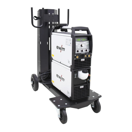
For your safety Part of the complete documentation Part of the complete documentation These operating instructions are part of the complete documentation and valid only in combination with all other parts of these instructions! Read and observe the operating instructions for all system components, especially the safety instructions! The illustration shows a general example of a welding system. -
Page 8: Machine Control - Operating Elements
Machine control – Operating elements Overview of control sections Machine control – Operating elements Overview of control sections For description purposes, the machine control has been divided into three sections (A, B, C) to ensure maximum clarity. The setting range for the parameter values are summarised in the parameter overview section >... -
Page 9: Control Section A
Machine control – Operating elements Overview of control sections 3.1.1 Control section A Figure 3-2 Item Symbol Description Welding data display (3-digit) Displays the welding parameters and the corresponding values > see 3.2 chapter Gas test push-button > see 4.1.1 chapter Operating mode >... - Page 10 Machine control – Operating elements Overview of control sections Item Symbol Description Display switching push-button kW ------- Welding power display V --------- Welding voltage display JOB ----- Display and setting of the JOB number with the control button Welding data display (3-digit) Displays the welding parameters and the corresponding values >...
-
Page 11: Control Section B
Machine control – Operating elements Overview of control sections 3.1.2 Control section B Figure 3-3 Item Symbol Description Parameter selection push-button, left The welding sequence parameters are selected one after another in an anti-clockwise direction. Control button Central control button to be pressed or turned > see 3.3 chapter. Parameter selection push-button, right The welding sequence parameters are selected one after another in a clockwise direction. -
Page 12: Control Section C
Machine control – Operating elements Machine display 3.1.3 Control section C Figure 3-4 Item Symbol Description AC frequency rotary knob (JOB 0) Balance AC balance rotary knob (JOB 0) Tungsten electrode diameter rotary knob (JOB 0) Machine display The following welding parameters can be displayed before (nominal values), during (actual values) or after welding (hold values): "left display"... -
Page 13: Welding Power Setting
Machine control – Operating elements Operating the machine control 3.3.2 Welding power setting The welding power is set using the control button. You can also adjust the parameters in the operation sequence or settings in the different machine menus. 3.3.3 Welding parameter setting in the operation sequence A welding parameter can be set in two ways in the operation sequence. -
Page 14: Functional Characteristics
Functional characteristics TIG welding Functional characteristics TIG welding Gas test – setting the shielding gas volume 4.1.1 • Slowly open the gas cylinder valve. • Open the pressure regulator. • Switch on the power source at the main switch. • Set the relevant gas quantity for the application on the pressure regulator. -
Page 15: Welding Task Selection
Functional characteristics TIG welding 4.1.2 Welding task selection The setting of the tungsten electrode diameter has a direct influence on the machine functionality, TIG ignition behaviour and minimum current limits. The ignition energy is controlled by the set electrode diameter. Smaller electrode diameters requires less ignition current and less ignition current time than greater electrode diameters. -
Page 16: Recurring Welding Tasks (Job 1-7)
Functional characteristics TIG welding 4.1.2.1 Recurring welding tasks (JOB 1–7) The user has 7 more memory locations at their disposal to save recurring or different welding tasks on a permanent basis. To do so, simply select the required memory location (JOB 1–7) and the welding task is set as described previously. -
Page 17: Tungsten Balling Function
Functional characteristics TIG welding 4.1.3.2 Tungsten balling function The tungsten balling function provides optimum tungsten balling, ensuring that the best ignition and welding results are achieved during AC welding. Optimum tungsten balling requires a sharpened electrode (about 15–25°) and the set electrode diameter on the machine control. -
Page 18: Alternating Current Waveforms
Functional characteristics TIG welding 4.1.3.3 Alternating current waveforms Selection EXIT Figure 4-5 Display Setting/selection Alternating current waveforms ------- Rectangular - Highest energy input (ex works) ------- Trapezoidal - An all-rounder, suitable for most applications ------- Sine - Low noise level 4.1.3.4 Automatic AC frequency Automatic AC frequency can be selected for JOB 1-100 only. -
Page 19: Arc Ignition
Functional characteristics TIG welding Selection < Figure 4-7 4.1.4 Arc ignition To change the ignition type, use parameter to switch between HF start ( ) and lift arc ( ) in the Expert menu > see 4.1.11 chapter. 4.1.4.1 HF ignition Figure 4-8 The arc is started without contact from high-voltage ignition pulses. -
Page 20: Liftarc
Functional characteristics TIG welding 4.1.4.2 Liftarc Figure 4-9 The arc is ignited on contact with the workpiece: a) Carefully place the torch gas nozzle and tungsten electrode tip onto the workpiece and press the torch trigger (liftarc current flowing, regardless of the main current set). b) Incline the torch over the torch gas nozzle to produce a gap of approx. -
Page 21: Operating Modes (Functional Sequences)
Functional characteristics TIG welding 4.1.5 Operating modes (functional sequences) 4.1.5.1 Explanation of symbols Symbol Meaning Press torch trigger 1 Release torch trigger 1 Current Time Gas pre-flow Ignition current Up-slope time Spot time Main current (minimum to maximum current) Secondary current AMP% Pulse time Pulse pause time... -
Page 22: Non-Latched Mode
Functional characteristics TIG welding 4.1.5.2 Non-latched mode Selection Figure 4-10 Sequence Figure 4-11 1st cycle: • Press torch trigger 1 and hold down. • Gas pre-flow time elapses. • HF ignition pulses jump from the electrode to the workpiece. The arc ignites. •... -
Page 23: Latched Mode
Functional characteristics TIG welding 4.1.5.3 Latched mode Selection Figure 4-12 Sequence Figure 4-13 099-00T402-EW501 24.04.2018... -
Page 24: Spotarc
Functional characteristics TIG welding cycle • Press torch trigger 1; gas pre-flow time elapses. • HF ignition pulses jump from the electrode to the workpiece. The arc ignites. • Welding current flows and immediately assumes the set ignition current (search arc at minimum setting). - Page 25 Functional characteristics TIG welding Figure 4-15 As an example the process is shown with HF ignition. Arc ignition with lift arc is also possible, however > see 4.1.4 chapter. Sequence: • Press torch trigger and hold down. • The gas pre-flow time elapses. •...
-
Page 26: Spotmatic
Functional characteristics TIG welding 4.1.5.5 spotmatic In contrast to the spotArc operating mode, the arc is not ignited by pressing the torch trigger as is usual, but by briefly touching the tungsten electrode against the workpiece. The torch trigger is used for welding process activation. -
Page 27: Tig Activarc Welding
4.1.6 TIG activArc welding The EWM activArc process, thanks to the highly dynamic controller system, ensures that the power supplied is kept virtually constant in the event of changes in the distance between the welding torch and the weld pool, e.g. during manual welding. Voltage losses as a result of a shortening of the distance between the torch and molten pool are compensated by a current rise (ampere per volt - A/V), and vice versa. -
Page 28: Pulse Welding
Functional characteristics TIG welding 4.1.8 Pulse welding The following pulse types can be selected: • Automated pulsing (TIG DC) • Thermal pulsing (TIG AC or TIG DC) • Metallurgical pulsing (TIG DC) • Average value pulses • AC special (TIG AC) 4.1.8.1 Automated pulses The automated pulsing pulse variant is only activated for DC welding in combination with the spotArc... -
Page 29: Pulsed Welding In The Upslope And Downslope Phases
Functional characteristics TIG welding Pulse time setting EXIT Figure 4-22 Pulse pause setting EXIT Figure 4-23 4.1.8.3 Pulsed welding in the upslope and downslope phases The pulse function can also be deactivated if necessary during the up-slope and down-slope phases (parameter ) >... -
Page 30: Average Value Pulse Welding
Functional characteristics TIG welding 4.1.9 Average value pulse welding A special feature with average value pulses is that the power source will always maintain the preset average value. This makes this method especially suitable for welding according to welding procedure specifications. - Page 31 Functional characteristics TIG welding Selection Figure 4-27 Balance setting EXIT Figure 4-28 Frequency setting EXIT Figure 4-29 099-00T402-EW501 24.04.2018...
-
Page 32: Ac Special
Functional characteristics TIG welding 4.1.9.2 AC special Is e.g. used to join metal sheets of different thickness. Figure 4-30 Figure 4-31 099-00T402-EW501 24.04.2018... -
Page 33: Welding Torch (Operating Variants)
Functional characteristics TIG welding 4.1.10 Welding torch (operating variants) Different torch versions can be used with this machine. Functions on the operating elements, such as torch triggers (BRT), rockers or potentiometers, can be modified individually via torch modes. Explanation of symbols for operating elements: Symbol Description Press torch trigger... -
Page 34: Standard Tig Torch (5-Pole)
Functional characteristics TIG welding 4.1.10.5 Standard TIG torch (5-pole) Standard torch with one torch trigger Figure Operating Explanation of symbols elements BRT1 = torch trigger 1 (welding current on/off; secondary current via tapping function) Functions Mode Operating elements Welding current on/off (ex works) Secondary current (latched operation) Standard torch with two torch triggers... - Page 35 Functional characteristics TIG welding Standard torch with one rocker (rocker, two torch triggers) Figure Operating Explanation of symbols elements BRT 1 = torch trigger 1 BRT 2 = torch trigger 2 Functions Mode Operating elements Welding current on/off Secondary current (ex works) Secondary current (tapping function) )/(latched operating mode)
-
Page 36: Tig Up/Down Torch (8-Pole)
Functional characteristics TIG welding 4.1.10.6 TIG up/down torch (8-pole) Up/down torch with one torch trigger Figure Operating Explanation of symbols elements BRT 1 = torch trigger 1 Functions Mode Operating elements Welding current on/off Secondary current (tapping function) )/(latched operating mode) (ex works) Increase welding current (up function Decrease welding current (down function... - Page 37 Functional characteristics TIG welding Up/down torch with two torch triggers Figure Operating Explanation of symbols elements BRT 1 = torch trigger 1 (left) BRT 2 = torch trigger 2 (right) Functions Mode Operating elements Welding current on/off Secondary current Secondary current (tapping function) )/(latched operating mode) (ex works) Increase welding current (up function...
-
Page 38: Potentiometer Torch (8-Pole)
Functional characteristics TIG welding 4.1.10.7 Potentiometer torch (8-pole) The welding machine needs to be configured for operation with a potentiometer torch > see 4.1.10.8 chapter. Potentiometer torch with one torch trigger Figure Operating Explanation of symbols elements BRT 1 = torch trigger 1 Functions Mode Operating... -
Page 39: 4.1.10.8 Configuring The Tig Potentiometer Torch Connection
Functional characteristics TIG welding 4.1.10.8 Configuring the TIG potentiometer torch connection DANGER Risk of injury due to electrical voltage after switching off! Working on an open machine can lead to fatal injuries! Capacitors are loaded with electrical voltage during operation. Voltage remains present for up to four minutes after the mains plug is removed. -
Page 40: Retox Tig Torch (12-Pole)
Functional characteristics TIG welding 4.1.10.9 RETOX TIG torch (12-pole) For operation with this welding torch, the welding machine must be equipped with the retrofit option "ON 12POL RETOX TIG" (12-pole torch connection socket)! Diagram Operating elements Explanation of symbols TT= torch trigger Functions Mode Operating... -
Page 41: Expert Menu (Tig)
Functional characteristics MMA welding 4.1.11 Expert menu (TIG) The Expert menu has adjustable parameters stored that don’t require regular setting. The number of parameters shown may be limited, e.g. if a function is deactivated. ENTER EXIT Figure 4-33 Display Setting/selection activArc parameter Parameter also adjustable after TIG activArc welding is activated. -
Page 42: Mma Welding
Functional characteristics MMA welding MMA welding 4.2.1 Welding task selection It is only possible to change the basic parameters when no welding current is flowing and any possible access control is disabled > see 4.4 chapter. The following welding task selection is an example of use. In general, the selection process always has the same sequence. -
Page 43: Hotstart Time
Functional characteristics MMA welding 4.2.2.2 Hotstart time EXIT Figure 4-37 4.2.3 Antistick The Antistick feature prevents the electrode from annealing. Should the electrode stick, the machine automatically switches to the minimum current within approx. one second. This prevents the electrode from annealing. -
Page 44: Average Value Pulse Welding
Functional characteristics Power-saving mode (Standby) 4.2.5 Average value pulse welding With average value pulsing, two currents are periodically toggled. The user can adjust the welding current (average current value AMP), pulse current Ipuls (parameter ), balance and frequency to the welding task. -
Page 45: Access Control
Functional characteristics Access control Access control The machine control can be locked to secure it against unauthorised or unintentional adjustment. The access block has the following effect: • The parameters and their settings in the machine configuration menu, Expert menu and operation sequence can only be viewed but not changed. -
Page 46: Machine Configuration Menu
Functional characteristics Machine configuration menu Machine configuration menu Basic machine settings are defined in the machine configuration menu. 4.6.1 Selecting, changing and saving parameters ENTER EXIT NAVIGATION Figure 4-42 099-00T402-EW501 24.04.2018... - Page 47 Functional characteristics Machine configuration menu Display Setting/selection Exit the menu Exit Torch configuration menu Set welding torch functions Torch mode (ex works 1) > see 4.1.10.2 chapter Up/down speed > see 4.1.10.3 chapter Increase value > rapid current change Decrease value > slow current change Current jump >...
- Page 48 Functional characteristics Machine configuration menu Display Setting/selection Error Error message after entering an incorrect machine code Access control – access code Setting: 000 to 999 (000 ex works) Machine code Querying the three-digit machine code (000 to 999), user input Error Error message after entering an incorrect machine code New machine code...
-
Page 49: Rectifying Faults
Rectifying faults Error messages (power source) Rectifying faults All products are subject to rigorous production checks and final checks. If, despite this, something fails to work at any time, please check the product using the following flowchart. If none of the fault rectification procedures described leads to the correct functioning of the product, please inform your authorised dealer. -
Page 50: Resetting Welding Parameters To The Factory Settings
Rectifying faults Resetting welding parameters to the factory settings Resetting welding parameters to the factory settings All customised welding parameters that are stored will be replaced by the factory settings. RESET Figure 5-1 Display Setting/selection Input confirmation User entries are applied, release button(s). Display machine control software version The query of the software versions only serves to inform the authorised service staff. -
Page 51: Parameter Overview - Setting Ranges
Appendix A Parameter overview – setting ranges Appendix A Parameter overview – setting ranges 6.1.1 TIG welding Name Display Setting range Main current AMP, depending on power source Gas pre-flow time Ignition current, percentage of AMP Ignition current, absolute, depending on power source Up-slope time 20,0 Pulse current... -
Page 52: Mma Welding
Appendix A Parameter overview – setting ranges 6.1.2 MMA welding Name Display Setting range Main current AMP, depending on power source Hot start current, percentage of AMP Hot start current, absolute, depending on power source Hot start time 10,0 Pulse current Pulse frequency Pulse balance Dynamic power adjustment... -
Page 53: Searching For A Dealer
Appendix B Searching for a dealer Appendix B Searching for a dealer Sales & service parteners www.ewm-group.com/en/specialist-dealers "More than 400 EWM sales partners worldwide" 099-00T402-EW501 24.04.2018...
Need help?
Do you have a question about the T 4.02 - AC/DC Comfort 2.0 and is the answer not in the manual?
Questions and answers