
Subscribe to Our Youtube Channel
Related Manuals for EWM Picomig 220 puls TKG


Summary of Contents for EWM Picomig 220 puls TKG
- Page 1 Operating instructions Welding machine Picomig 220 puls TKG Picomig 220 Synergic TKG 099-005680-EW501 Observe additional system documents! 15.2.2023...
- Page 2 +49 2680 181-0. A list of authorised sales partners can be found at www.ewm-group.com/en/specialist-dealers. Liability relating to the operation of this equipment is restricted solely to the function of the equipment. No other form of liability, regardless of type, shall be accepted.
- Page 3 Contents Notes on using these operating instructions 099-005680-EW501 15.2.2023...
-
Page 4: Table Of Contents
Safety instructions ........................7 Transport and installation ..................... 11 3 Intended use ..........................13 Applications .......................... 13 3.1.1 Picomig 220 puls TKG ..................13 3.1.2 Picomig 220 Synergic TKG .................. 13 Documents which also apply ....................13 3.2.1 Warranty ....................... 13 3.2.2... - Page 5 Contents Notes on using these operating instructions Checklist for rectifying faults ....................39 Dynamic power adjustment ....................40 Resetting welding parameters to the factory settings ............41 8 Technical data ..........................42 Picomig 220 ......................... 42 9 Accessories ..........................43 Transport system .........................
-
Page 6: For Your Safety
For your safety Notes on using these operating instructions For your safety Notes on using these operating instructions DANGER Working or operating procedures which must be closely observed to prevent imminent serious and even fatal injuries. • Safety notes include the "DANGER" keyword in the heading with a general warning symbol. •... -
Page 7: Safety Instructions
For your safety Safety instructions Symbol Description Symbol Description Indicates technical aspects which the Activate and release / Tap / Tip user must observe. Switch off machine Release Switch on machine Press and hold Incorrect / Invalid Switch Correct / Valid Turn Input Numerical value –... - Page 8 For your safety Safety instructions WARNING Risk of accidents due to non-compliance with the safety instructions! Non-compliance with the safety instructions can be fatal! • Carefully read the safety instructions in this manual! • Observe the accident prevention regulations and any regional regulations! •...
- Page 9 For your safety Safety instructions WARNING Risk of injury due to improper clothing! During arc welding, radiation, heat and voltage are sources of risk that cannot be avoided. The user has to be equipped with the complete personal protective equipment at all times.
- Page 10 For your safety Safety instructions CAUTION Smoke and gases! Smoke and gases may lead to shortness of breath and poisoning! The ultraviolet radia- tion of the arc may also convert solvent vapours (chlorinated hydrocarbon) into poiso- nous phosgene. • Ensure sufficient fresh air! •...
-
Page 11: Transport And Installation
For your safety Transport and installation CAUTION Obligations of the operator! The respective national directives and laws must be complied with when operating the machine! • Implementation of national legislation relating to framework directive 89/391/EEC on the int- roduction of measures to encourage improvements in the safety and health of workers at work and associated individual guidelines. - Page 12 For your safety Transport and installation CAUTION Risk of accidents due to supply lines! During transport, attached supply lines (mains leads, control cables, etc.) can cause risks, e.g. by causing connected machines to tip over and injure persons! • Disconnect all supply lines before transport! Risk of tipping! There is a risk of the machine tipping over and injuring persons or being damaged itself during movement and set up.
-
Page 13: Intended Use
3.2.1 Warranty For more information refer to the "Warranty registration" brochure supplied and our information regarding warranty, maintenance and testing at www.ewm-group.com! 3.2.2 Declaration of Conformity This product corresponds in its design and construction to the EU directives listed in the decla- ration. -
Page 14: Part Of The Complete Documentation
Intended use Documents which also apply 3.2.6 Part of the complete documentation This document is part of the complete documentation and valid only in combination with all other parts of these instructions! Read and observe the operating instructions for all system components, especially the safety instructions! The illustration shows a general example of a welding system. -
Page 15: Machine Description - Quick Overview
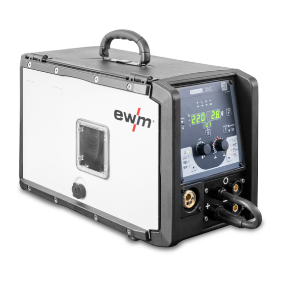
Machine description – quick overview Front view Machine description – quick overview Front view Figure 4-1 099-005680-EW501 15.2.2023... - Page 16 Machine description – quick overview Front view Item Symbol Description Carrying handle Machine control (see the relevant control operating instructions) Welding torch connection (Euro torch connector) Welding current, shielding gas and torch trigger integrated Connection socket, "+" welding current • ---------- MIG/MAG cored wire welding: Workpiece connection •...
-
Page 17: Inside View
Machine description – quick overview Inside view Inside view Figure 4-2 099-005680-EW501 15.2.2023... - Page 18 Machine description – quick overview Inside view Item Symbol Description Rotary closure Locking of the protective cap Wire spool inspection window Check wire supply Protective cap Cover for the wire feed mechanism and other operating elements. Depending on the machine series, additional stickers with information on the replace- ment parts and JOB lists will be located on the inside.
-
Page 19: Design And Function
Design and function Transport and installation Design and function WARNING Risk of injury from electrical voltage! Contact with live parts, e.g. power connections, can be fatal! • Observe the safety information on the first pages of the operating instructions! • Commissioning must be carried out by persons who are specifically trained in handling power sources! •... -
Page 20: Workpiece Lead, General
Design and function Transport and installation 5.1.3 Workpiece lead, general CAUTION Risk of burning due to incorrect welding current connection! If the welding current plugs (machine connections) are not locked or if the workpiece connection is contaminated (paint, corrosion), these connections and leads can heat up and cause burns when touched! •... -
Page 21: Stray Welding Currents
Design and function Transport and installation • Use an individual welding lead to the workpiece for each welding machine! Figure 5-2 • Fully unroll welding current leads, torch hose packages and intermediate hose packages. Avoid loops! • Always keep leads as short as possible! Lay any excess cable lengths in meanders. -
Page 22: Mains Connection
Design and function Transport and installation WARNING Risk of injury due to stray welding currents! Stray welding currents can destroy protective earth conductors, damage machines and electronic devices and cause overheating of components, leading to fire. • Check that all welding current connections are firmly secured and electrical connections are in perfect condition. -
Page 23: Mains Configuration
Design and function Transport and installation DANGER Hazards caused by improper mains connection! An improper mains connection can cause injuries or damage property! • The connection (mains plug or cable), the repair or voltage adjustment of the device must be carried out by a qualified electrician in accordance with the respective local laws or nati- onal regulations! •... -
Page 24: Pressure Regulator Connection
Design and function Transport and installation WARNING Risk of injury due to improper handling of shielding gas cylinders! Improper handling and insufficient securing of shielding gas cylinders can cause serious injuries! • Place shielding gas cylinder into the designated holder and secure with fastening elements (chain/belt)! •... -
Page 25: Shielding Gas Hose Connection
Design and function Transport and installation 5.1.7.2 Shielding gas hose connection Figure 5-7 Item Symbol Description Connection thread - G¼" Shielding gas connection (inlet) • Screw the gas hose connection to the shielding gas connection (inlet) on the machine gas-tight. 5.1.7.3 Gas test –... -
Page 26: Mig/Mag Welding
Design and function MIG/MAG welding MIG/MAG welding 5.2.1 Welding torch and workpiece line connection On delivery, the Euro torch connector is fitted with a capillary tube for welding torches with a steel liner. Conversion is necessary if a welding torch with a liner is used! •... -
Page 27: Wire Feed
Design and function MIG/MAG welding Choose welding current connection socket according to the signal light for the polarity setting! • Select JOB > see 5.2.3 chapter • Polarity selection “+” or polarity selection “-” signal lights show the polarity setting. Figure 5-8 Item Symbol Description... -
Page 28: Inserting The Wire Spool
Design and function MIG/MAG welding CAUTION Risk of injury due to moving parts! The wire feeders are equipped with moving parts, which can trap hands, hair, clothing or tools and thus injure persons! • Do not reach into rotating or moving parts or drive components! •... -
Page 29: Changing The Wire Feed Rollers
Design and function MIG/MAG welding • Unlock and open protective flap. • Loosen knurled nut from spool holder. • Fix welding wire reel onto the spool holder so that the carrier pin locks into the spool bore. • Fasten wire spool using knurled nut. Figure 5-10 Observe the unwinding direction of the wire spool. -
Page 30: Spool Brake Setting
Design and function MIG/MAG welding Figure 5-12 Item Symbol Description Adjusting nut Feed roll tensioner Fixing the clamping unit and setting the pressure. Clamping unit Knurled screw Drive roller Guide tube Wire feed nipple Pressure roller • Extend and lay out the torch hose package. •... -
Page 31: Welding Task Selection
Design and function MMA welding Item Symbol Description Allen screw Securing the wire spool retainer and adjustment of the spool brake • Tighten the Allen screw (8 mm) in the clockwise direction to increase the braking effect. Tighten the spool brake until the wire spool no longer turns when the wire feed motor stops but without it jamming during operation! 5.2.3 Welding task selection... -
Page 32: Welding Task Selection
Design and function TIG welding • Insert the polarity selection plug in the park socket and lock in place by turning to the right. • Insert the electrode holder plug and workpiece lead into the welding current socket depending on ap- plication and lock in place by turning to the right. -
Page 33: Welding Task Selection
Design and function TIG welding 5.4.3 Welding task selection For selection of the welding task and for general operation see the relevant Control operating instructions. 099-005680-EW501 15.2.2023... -
Page 34: Maintenance, Care And Disposal
Maintenance, care and disposal General Maintenance, care and disposal General DANGER Risk of injury due to electrical voltage after switching off! Working on an open machine can lead to fatal injuries! Capacitors are loaded with electrical voltage during operation. Voltage remains present for up to four minutes after the mains plug is removed. -
Page 35: Explanation Of Icons
Maintenance, care and disposal Explanation of icons Explanation of icons Personnel Welder / operator Qualified person (authorised service personnel) Tests Visual inspection Functional test Period, interval One-shift operation Multi-shift operation Every 8 hours Daily Weekly Monthly Every 6 months Annually Maintenance schedule Maintenance step Only personnel designated as inspectors or repairers due to their trai-... - Page 36 Maintenance, care and disposal Maintenance schedule Maintenance step Only personnel designated as inspectors or repairers due to their trai- ning are allowed to carry out the relevant work step! Non-applicable in- spection points are omitted. • Checking the welding system for damage to the housing. •...
-
Page 37: Disposing Of Equipment
Information on returning used equipment or collections can be obtained from the respective municipal administration office. Devices can also be returned to EWM sales partners across Europe. Further information on the topic of the disposal of electrical and electronic equipment can be found on our website at: https://www.ewm-group.com/de/nachhaltigkeit.html. -
Page 38: Rectifying Faults
Rectifying faults Software version of the machine control Rectifying faults All products are subject to rigorous production checks and final checks. If, despite this, something fails to work at any time, please check the product using the following flowchart. If none of the fault rectification procedures described leads to the correct functioning of the product, please inform your authorised dea- ler. -
Page 39: Checklist For Rectifying Faults
Rectifying faults Checklist for rectifying faults Error message Possible cause Remedy Electronics error Switch the machine off and on again. If the error persists, notify service department Temperature error Allow the machine to cool down Motor fault Check wire feed mechanism, switch the machine off and on again, inform the service department if the fault persists. -
Page 40: Dynamic Power Adjustment
Rectifying faults Dynamic power adjustment Functional errors Mains fuse triggers - unsuitable mains fuse Set up recommended mains fuse > see 8 chapter. Machine does not start up after switching on (device fan and possibly coolant pump have no function). Connect the control cable of the wire feeder. -
Page 41: Resetting Welding Parameters To The Factory Settings
Rectifying faults Resetting welding parameters to the factory settings Resetting welding parameters to the factory settings All customised welding parameters that are stored will be replaced by the factory settings. RESET Figure 7-1 Display Setting/selection Calibration The machine will be calibrated for approx 2 seconds each time it is switched on. Initialising Keep the push-button pressed until is shown on the display. -
Page 42: Technical Data
Technical data Picomig 220 Technical data Picomig 220 Performance specifications and guarantee only in connection with original spare and replacement parts! MIG/MAG Welding current (I 5 A to 220 A 5 A to 230 A 5 A to 180 A Welding voltage according to stan- 14,3 V to 25,0 V 10,2 V to19,2 V... -
Page 43: Accessories
Accessories Transport system Accessories Performance-dependent accessories like torches, workpiece leads, electrode holders or intermediate hose packages are available from your authorised dealer. Transport system Type Designation Item no. ON Trolly Picomig Trolly Picomig 180 with holder for 300 mm wire 092-000312-00000 spool ON WAK D.09/D.12/T.05... -
Page 44: Replaceable Parts
Replaceable parts Wire feed rollers Replaceable parts The manufacturer's warranty becomes void if non-genuine parts are used! • Only use system components and options (power sources, welding torches, electrode hold- ers, remote controls, spare parts and replacement parts, etc.) from our range of products! •... - Page 45 Replaceable parts Wire feed rollers Type Designation Item no. URUE VERZ>UNVERZ FE/AL Conversion kit, 37mm, 4-roller drive on non-toothed 092-000415-00000 4R SF rollers (steel/aluminium) URUE ROE 2DR4R Conversion kit, 37 mm, 4-roller drive for cored wire 092-000410-00000 0,8/0,9+0,8/0,9 SF URUE ROE 2DR4R Conversion kit, 37 mm, 4-roller drive for cored wire 092-000411-00000 1,0/1,2+1,4/1,6 SF...
-
Page 46: Appendix
Appendix Searching for a dealer Appendix 11.1 Searching for a dealer Sales & service partners www.ewm-group.com/en/specialist-dealers "More than 400 EWM sales partners worldwide" 099-005680-EW501 15.2.2023...
Need help?
Do you have a question about the Picomig 220 puls TKG and is the answer not in the manual?
Questions and answers