
Subscribe to Our Youtube Channel
Related Manuals for Miranda EC9535


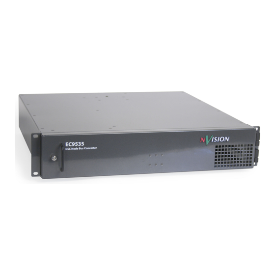
Summary of Contents for Miranda EC9535
- Page 1 EC9535 GSC Node Bus Converter User’s Guide Miranda Technologies Inc. 3499 Douglas B. Floreani Montreal, Quebec Canada H4S 2C6...
-
Page 2: Fcc Statement
The information and intellectual property contained herein is confidential between Miranda and the client and remains the exclusive property of Miranda. If you find any problems in the documentation, please report them to us in writing. Miranda does not warrant that this document is error-free. -
Page 3: Technical Support Contact Information
Contact Miranda for details on the software license agreement and product warranty. Technical Support Contact Information Miranda has made every effort to ensure that the equipment you receive is in perfect working order and that the equipment fits your needs. In the event that problems arise that you cannot resolve, or... - Page 4 Change History The table below lists the changes to the EC9535 GSC Node Bus Converter User’s Guide. • User’s Guide Part # UG0050-00 • Software version: -na- Date Description Approved By 14 Dec 09 16272 Initial release • Restriction on Hazardous Substances (RoHS) Miranda is in compliance with EU Directive RoHS 2002/95/EC governing the restricted use of cer- tain hazardous substances and materials in products and in our manufacturing processes.
- Page 5 The fuse symbol indicates that the fuse referenced in the text must be replaced with one having the ratings indicated. The presence of this symbol in or on Miranda equipment means that it has been designed, tested and certified as complying with applicable Underwriter’s Laboratory (USA) regulations and rec- ommendations.
- Page 6 General Warnings A warning indicates a possible hazard to personnel which may cause injury or death. Observe the following general warnings when using or working on this equipment: • Heed all warnings on the unit and in the operating instructions. •...
-
Page 7: Table Of Contents
How to Rack Mount the EC9535 ........ - Page 8 Table of Contents Chapter 5 Technical Details ............23 Chapter 6 Glossary.
-
Page 9: Introduction
(3.47 inches, 88.1 mm), and 16.0 inches (406 mm) deep. When placing the rack in your facility, be sure to leave enough space for air flow through the front and rear of the EC9535 and within easy access of an AC power source. For mounting instructions, see Rack Mount on page 10. -
Page 10: Power Supply
DC output; no voltage selection is required. Frame Front The front of the EC9535 GSC Node Bus Converter features a single door. When facing the front of the frame the right-hand side features an open grill through which a fan draws cooling air. A handle is provided on the left-hand side. -
Page 11: Rear Connections
GSC Node Bus Control Connections The EC9535 GSC Node Bus Converter has one port labeled ‘GSC NODE BUS’, as shown in Figure 1-4. This connection is used to connect a SMS7000 system controller to the EC9535. In turn, the EC9535 is connected to a NV8288, NV8288-Plus or NV8500 Family router. -
Page 12: Diagnostic Connections
Figure 1-5. Serial Control Connections (Rear View) Diagnostic Connections The diagnostic connections enable the EC9535 to communicate with the UniConfig application. UniConfig runs on a PC separate from the EC9535 and is used to perform system setup tasks, and configure and monitor EC9535. (See Configuration on page 19.) See also the UniConfig User’s... -
Page 13: Aes Reference Connections
In order for EC9535 to communicate with UniConfig through an Ethernet connection, you must configure an IP address for each of EC9535’s control cards. The IP address is set using UniConfig. However, UniConfig runs on a PC and cannot communicate with EC9535 until an IP address has been entered. -
Page 14: Video Reference
Figure 1-10. Time Code Reference Connection (Rear View) System Alarm The EC9535 has a system alarm that sends notification of a malfunction, such as when a fan or power supply is not functioning properly. The alarm connection can be connected to external equip- ment that display visual signals when an alarm is activated. - Page 15 1. Introduction Rear Connections The alarm connection is labeled ‘ALARMS’ and is located on the rear of the EC9535, as shown in Figure 1-11. For instructions on making alarm connections, see Making System Alarm Connec- tions on page 15. TIME...
- Page 16 1. Introduction Rear Connections Rev 1.0 • 14 Dec 09...
-
Page 17: Installation
2. Installation When setting up an EC9535 GSC Node Bus Converter for the first time, or reconfiguring an exist- ing configuration, there are certain steps that must be performed. It is recommended that initial installation and later reconfiguration tasks be performed in a specific order to avoid possible com- plications. -
Page 18: Preparing For Installation
How to Rack Mount the EC9535 1 Determine the placement of the EC9535 and the rack in the facility. When placing the frame and rack, be sure to locate the rack near an accessible AC source power outlet. The AC source is used to power the frame. -
Page 19: How To Install Control Cards
EC9535. The SMS7000 system controller is connected using the ‘GSC NODE BUS’ connection located on the rear of the EC9535 frame. The connection uses a 75 Ω BNC connector and coaxial cable. -
Page 20: Making Router Connections
In order for a NV8288, NV8288-Plus or NV8500 Family router to communicate with a SMS7000 system controller, the router must be connected to an EC9535. The router is connected using the serial control system connections, located on the rear of the EC9535, and a cable provided by Miranda (WC0152). -
Page 21: Making Diagnostic Connections
There are two sets of diagnostic connections: one set is located on the front of the control cards and one set is located on the rear of the EC9535, labeled ‘DIAG’. Which is used is entirely up to you and your facility needs. Usually the control card connection is used when the diagnostic connection to UniConfig is temporary. -
Page 22: Frame Diagnostic Connections
38400 baud, RS-232. For more information, see the UniConfig User’s Guide. How to Make Frame Diagnostic Connections 1 Locate the diagnostic connections on the rear of the EC9535, as shown in Figure 2-5. The diag- nostic connections are labeled ‘DIAG’. -
Page 23: Making System Alarm Connections
3. Making System Alarm Connections The EC9535 provides a system alarm that notifies you of a malfunction, such as when a fan or power supply is not functioning properly. And alarm can be connected to an external alarm indica- tor that displays visual cues when the alarm is activated. -
Page 24: Alarm Indicator Equipment
An external alarm indicator can be created to display visual cues when a failure has occurred on the EC9535 frame. LEDs can be wired to specific pins on a DE9 connector such that each LED indi- cates what specific router module has failed. -
Page 25: How To Connect To Power
4 Repeat step 2 and step 3 for the ‘PS2 48V’ connection. 5 Connect the EC9535’s ground lug to earth ground using a copper wire from 14 to 6 AWG. The ground lug is located in the lower right corner of the frame, as shown in Figure 2-8 on page 17. - Page 26 2. Installation Connecting to Power Rev 1.0 • 14 Dec 09...
-
Page 27: Configuration
EC9535, see the section “Configuring EC9535” within the UniConfig User’s Guide. When configuring the EC9535, the EC9535’s ‘CTRL 1’ serial port must be set to the same baud rate as the controlled router’s ‘CTRL 1’ serial port rate. (See... - Page 28 3. Configuration Rev 1.0 • 14 Dec 09...
-
Page 29: Maintenance
4. Maintenance The EC9535 does not require any periodic electrical or physical maintenance. However, it is rec- ommended that the system’s indicator LEDs be checked on a regular basis to ensure that the system is operating properly. (See Indicator LEDs on page 21.) It is also a good idea to regularly make sure... -
Page 30: Air Flow
Air Flow A fan in the EC9535 frame draws cooling air from the front of the frame, through the door, and exhausts heated air through the rear. The EC9535 must have the door correctly installed and closed for proper airflow through the chassis. -
Page 31: Technical Details
5. Technical Details This section provides technical specifications for the of routers and the EC9535. Power Specifications Type Parameters AC input 90–130/180–250 VAC, 50/60 Hz, auto-ranging AC fuses No user serviceable fuses AC connectors 2, PS0007 AC power usage 40 Watts, maximum... -
Page 32: Environmental Specifications
5. Technical Details Environmental Specifications Type Parameter Operating temperature 0 to 40° Centigrade Relative humidity 0 to 90%, non-condensing Audio Specifications Type Parameter Audio Reference Input Type Serial digital audio Standard AES3id Sample Rate 48 kHz Connector 2, BNC (redundant) 75 Ω... -
Page 33: Glossary
3 levels: video, AES, and time code. A hypothetical device in this system is Camera 1, which consists of video on input port 1 of the video router, AES on input port 5 of the AES router, and time code on input port 8 of the time code router. (The EC9535 does presently include time-code routers.). - Page 34 Converter switches one type, or level, of a device’s signal set. Physically Matrix modules are said to be in physically contiguous slots in a EC9535 frame when both the Contiguous inputs and outputs associated with those slots are in numerical sequence. For example, input slots 5 and 6 are physically contiguous because inputs 1-16 and 17-32 are in numerical sequence.
- Page 35 A device can be both a source and destination. An example of such a device is a VTR. (Super Wide Band). A term originated by Miranda that refers to the ability of a router to pass a wide range of digital bit rates and formats. Miranda’s SWB supports data rates from about 15 Mb/s to 1.5 GB/s.
- Page 36 6. Glossary Rev 1.0 • 14 Dec 09...
-
Page 37: Appendix A Part Numbers
7. Part Numbers This appendix provides a list of parts provided by Miranda for the EC9535. Part Number Description PS0007 AC to 48V DC Power supply EM0374 Control card SM0220 Mezzanine on control card for SMS7000 system controllers WC0152 Proprietary router control system cable with 4 DB9 connectors. - Page 38 7. Part Numbers Rev 1.0 • 14 Dec 09...
-
Page 39: Index
ESD, defined ......4 Diagnostic EC9535 GSC Node Bus Converter • User’s Guide... - Page 40 ......4 Ethernet connection Miranda ....25 .
- Page 41 ......10 XP, Windows EC9535 GSC Node Bus Converter • User’s Guide...
- Page 42 Index Rev 1.0 • 14 Dec 09...
Need help?
Do you have a question about the EC9535 and is the answer not in the manual?
Questions and answers