Table of Contents

Related Manuals for Comet T8348


Summary of Contents for Comet T8348
- Page 1 Instruction Manual T8348 programmable indoor transmitter of temperature and CO concentration with RS232 serial output T8448 programmable indoor transmitter of temperature and CO concentration with RS485 serial output...
- Page 2 © Copyright: COMET System, Ltd. It is prohibited to copy and make any changes in this manual, without explicit agreement of company COMET System, Ltd. All rights reserved. COMET System, Ltd. makes constant development and improvement of their products. Manufacturer reserves the right to make technical changes to the device without previous notice.
-
Page 3: Table Of Contents
Table of contents GENERAL DESCRIPTION ................. 4 DEVICE SETTING FROM THE MANUFACTURER ........6 DEVICE INSTALLATION ................7 INFO MODE ....................9 DESCRIPTION OF COMMUNICATION PROTOCOLS ......10 MODBUS RTU ..................10 PROTOCOL COMPATIBLE WITH ADVANTECH-ADAM STANDARD ...12 ARION COMMUNICATION PROTOCOL - AMIT COMPANY ....13 TROUBLESHOOTING ................ -
Page 4: General Description
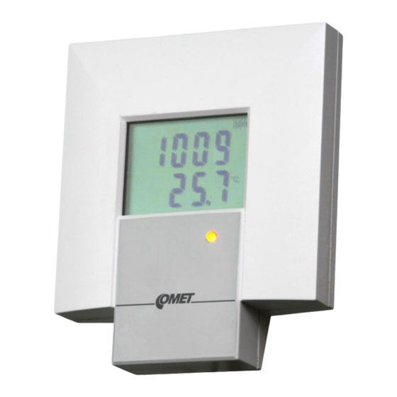
The transmitters are designed for online measurement of carbon dioxide concentration and temperature of air in a building interiors. device type construction type output galvanic isolated output T8348 ambient air RS232 T8448 ambient air RS485 The CO2 concentration is measured using the dual wavelength NDIR sensor with multiple point adjustment. - Page 5 Use software Tsensor for setting of all device parameters (recommended). It is free to download at www.cometsystem.cz. It supports make the adjustment of the device too. This procedure is described at file „Calibration manual.pdf“ which is installed commonly with the software. Change of some parameters is possible to do without user’s software with Windows hyperterminal...
-
Page 6: Device Setting From The Manufacturer
Device setting from the manufacturer If special setting was not required in the order device is set from the manufacturer to the following parameters: communication protocol: Modbus RTU device address: communication speed: 9600Bd, without parity, 2 stop bits display: switched ON value displayed at higher line: CO concentration value displayed at lower line: temperature... -
Page 7: Device Installation
Device installation Devices are designed for indoor applications. It is recommended to mount them on universal wiring box (common installation box KU68) with using two enclosed mounting screws. For correct function there is necessary to find proper device place. It shouldn’t be placed at places where it can be affected by sunshine, near radiators, heating elements and other heat sources, air handlers, windows, doors, into racks and shelves and similar places. - Page 8 Device demounting If there is necessary demount the device, insert flat bladed screwdriver max. 3.5 mm wide from top side into middle device’s air hole. There is fastening member placed, insert screwdriver beyond the fastening member about 2 cm deep. Then slightly move screwdriver in arrow direction, it unlock fastening member and the device is partially opened.
-
Page 9: Info Mode
Info mode If in doubt of setting of installed device, verification of its address is enabled even without using computer. Power supply should be connected and jumper should be opened. Jumper is accessible after removing the front part of device (jumper is placed at the right bottom corner at the same side as button). -
Page 10: Description Of Communication Protocols
Description of communication protocols Detailed description of each communication protocols including examples of communication is available in individual document “Description of communication protocols” which is available at www.cometsystem.cz (see appropriate transmitter pages). Note: After switching on the power of the device it can last up to 2 s before the device starts to communicate and measure! Modbus RTU Control units communicate on master-slave principle in half-duplex... - Page 11 Jumper closed – writing to device memory is enabled by means of User’s software Jumper opened and button shortly pressed – device goes to Info mode, see chapter „Info mode“ Jumper closed and button pressed for longer than six seconds – causes restoring of manufacturer setting of communication protocol, i.e.
-
Page 12: Protocol Compatible With Advantech-Adam Standard
register is designed for writing, for details see description of communication protocols register addresses are indexed from zero – register 0x31 is physically sent as value 0x30, 0x32 as 0x31 (zero based addressing). Note: In case there is a need for reading of measured values from the device with higher resolution than one decimal, measured values in device are stored also in „Float“... -
Page 13: Arion Communication Protocol - Amit Company
If jumper during switching ON the power is not closed, device communicates in accordance with stored setting. Communication speed and check sum are possible to change only if jumper is closed. Jumper closed and button pressed for longer than six seconds – causes restoring of manufacturer setting of communication protocol, i.e. -
Page 14: Troubleshooting
Troubleshooting Error states of the device Device continuously checks its state during operation. In case error is found LCD displays corresponding error code: Error 0 - first line displays „Err0“. Check sum error of stored setting inside device’s memory. This error appears if incorrect writing procedure to device’s memory occurred or if damage of calibration data appeared. -
Page 15: Technical Data
Technical data Measured values concentration: ± (50 ppm + 2 % of measuring value) at 25 °C Accuracy: (77 °F) and 1013 hPa Range: 0 to 2000 ppm / ºC in the range 0 to +50 ºC Temperature depend.: typ. 2 ppm CO (32 to 122 °F) Long term stability: typ. -
Page 16: Operating Conditions
Recommended calibration interval: 2 years concentration 5 years, temperature 2 years Storage temperature range: -40 to +60 °C (-40 to 140 ºF) Storage relative humidity range: 5 to 95 %RH (no condensation) Storage pressure range: 700 to 1100 hPa Electromagnetic compability: EN 61326-1 Weight: approximately 150 g... -
Page 17: Dimensions
Dimensions Typical application wiring T8348 T8448 IE-SNC-T83(4)48-03... -
Page 18: Appendix A
Appendix A Connection of T8448 transmitter to the PC The ELO E214 converter is an optional accessory for connection of transmitter with RS485 interface to the PC via USB port. Link RS485 is connected across pin 9 A(+) and pin 8 B(-). The pull up, pull down and termination resistors are part of the transmitter.
Need help?
Do you have a question about the T8348 and is the answer not in the manual?
Questions and answers