Table of Contents
Advertisement
Quick Links
Advertisement
Table of Contents

Related Manuals for Comet T3411


Summary of Contents for Comet T3411
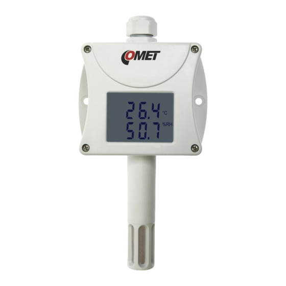
- Page 1 TRANSMITTER T3311, T3411 Programmable relative humidity and temperature transmitter with serial output RS232 and RS485 With computing of dew point temperature, absolute humidity, specific humidity, mixing ratio and specific enthalpy Instruction Manual...
-
Page 2: Table Of Contents
Transmitter setting from the manufacturer....................3 Transmitter installation ..........................3 Dimensions............................. 4 Typical application wiring, connection of terminals................5 Info mode ............................... 6 Setting of transmitter, selection of communication protocol ..............6 Description of communication protocols ....................8 Modbus RTU............................8 Supported functions ........................... -
Page 3: Transmitter Setting From The Manufacturer
4 seconds interval. Display can be also switched OFF totally. Output link RS485 of transmitter T3411 is galvanic isolated. Output link RS232 of transmitter T3311 is NOT galvanic isolated. Setting of all transmitter parameters is enabled in accordance with procedure described in chapter „Setting of transmitter, selection of communication protocol“... -
Page 4: Dimensions
The cable should not be led in parallel along power cabling. Safety distance is up to 0.5 m, otherwise undesirable induction of interference signals can appear. Dimensions T3311 – RS232 T3411 – RS485 IE-SNC-T33(4)11-04... -
Page 5: Typical Application Wiring, Connection Of Terminals
Typical application wiring, connection of terminals T3311 – power from communication port T3311 – power from external voltage source T3411 – RS485 IE-SNC-T33(4)11-04... -
Page 6: Info Mode
(providing all settings of transmitter parameters) or proceed in following way (support basic setting): • Connect transmitter with PC, for T3411 (RS485) use converter RS485/RS232. • Run program „HyperTerminal“ on your computer – it is a part of Windows operating system (Start →... - Page 7 • Select item „File“, „Features“ in menu. Select bookmark „Setup“, in the window, click on „ASCII Setup... “ and modify all items in accordance with following figure and press OK • Unscrew 4 screws of transmitter cover and remove it. Plug in jumper. •...
-
Page 8: Description Of Communication Protocols
Select required items to set the transmitter: 0 … Displays actual setting of the transmitter 1 … Selection of communication protocol and setting of its parameters (transmitter address, communication speed…). For entering numeric values use digits 0 to 9 and characters „A“... -
Page 9: Description Of Supported Function
• Jumper opened and button shortly pressed – transmitter goes to Info mode, see chapter „Info mode“ Description of supported function 03 (0x03): Reading of 16-bit registers (Read Holding Registers) Function serves for reading of values from transmitter. Addresses of available registers are listed in chapter „Modbus registers of the transmitter on page 13.“... - Page 10 important settings stored in transmitter can occur! It is strongly recommended to use User’s software to set all transmitter’s parameters or use procedure described in chapter „Setting of transmitter, selection of communication protocol“ for transmitter setting instead. Request: ----------------------------------------------------------------------------------------------------- FUNCTION Function code 0x10 ----------------------------------------------------------------------------------------------------- DATA...
- Page 11 1. Close jumper located next to connection terminals of the transmitter. 2. Read entire area 0x2001 to 0x2040 to master device. At address 0x2040 check sum of entire area is stored. It is calculated as sum of 16bit values from addresses 0x2001 to 0x2039. Stored are lowest 16 bits of this sum - enables to check correct reading of the area.
-
Page 12: Exception Responses
01 10 20 00 00 40 80 00 9F 00 24 00 00 30 30 3B 4B 77 D3 BD 35 00 00 00 00 00 00 00 00 00 00 00 00 00 00 00 00 00 00 00 00 00 00 00 00 00 00 00 00 00 00 00 00 00 00 84 70 00 00 86 2A 00 00 84 44 AA 80 85 07 A8 D0 57 7E 5F 94 F3 DC 00 12 2E DD 78 0C 40 AA 77 D3 F2 C4 00 12 17 78 77 F5 F3 EC 00 12 ED BF 77 D5 4F 10 77 D8 FF FF FF FF 40 DE 77 D3 2E F7 78 0C 06 5C 00 01 00 00 00 00 F3 DC 00 12 42 9F 52 3A 61 22... -
Page 13: Procedure During Calculation Of Modbus Crc
Procedure during calculation of Modbus CRC 1. To fill 16-bit register with value 0xFFFF (all bits set to 1). Let us call this register „CRC register“. 2. Perform logic function Exclusive OR with first eight bit message Byte with lower eight bits of CRC register. -
Page 14: Reading Of Relative Humidity, Address 0X0032
Received response from transmitter: 01 03 02 00 F4 B9 C3 address transmitter: reading 16-bit registers Number Byte State of register Hi State of register Lo (0x00F4 = 244 = 24.4 °C) Modbus CRC Lo Modbus CRC Hi Reading of relative humidity, address 0x0032 Modbus command: address transmitter: reading 16-bit registers... -
Page 15: Protocol Compatible With Advantech-Adam Standard
initial address Lo number read registers Hi number read registers Lo Via link is physically sent: 01 03 00 30 00 03 05 C4 Received response from transmitter: 01 03 06 FF C4 01 14 FF 38 C5 71 transmitter address: reading 16-bit registers Number Byte State of register Hi... -
Page 16: Description Of Supported Functions
Description of supported functions Configuration of transmitter Syntax of command: %AANNTTCCFF cr Meaning of symbols: AA … current address of transmitter 00…FF (hexadecimal) NN … new address of transmitter 00…FF (hexadecimal) TT … code of transmitter (2Ch…combined transmitter of temperature and humidity) CC ... -
Page 17: Reading Of Computed Value
Reading of computed value Syntax command: #AA2 cr Response: > (computed value) cr (e.g. >+004.30 cr) Query to adjusted configuration Syntax command: $AA2 cr Response: symbols correspond with paragraph !AATTCCFF cr "Configuration of transmitter" Reading of device name Syntax command: $AAM cr Response: (accordingly with transmitter... -
Page 18: Format Of Data
Format of data Transmitter uses data format „Engineering units“, i.e. fixed decimal point. Temperature, humidity and computed value are displayed with 2 digits behind decimal point, second digit behind decimal point is always zero General writing: „>±xxx.x0 cr“ Examples: >-050.20 cr >+000.00 cr >+025.80 cr Error states... -
Page 19: Supported Function Description
Supported function description 0x24 MODE – Set mode Device supports next modes: 0x00, 0x01 Simplex 0x02, 0x03 Half Duplex over RS232, RS485 line Lost of connection detection (Guard time) is always set to zero, it means lost of connection is not detected, guard time value sent by command is not important, it is not checked. -
Page 20: Error 2
• Relative humidity is higher than 100%, i.e. damaged humidity sensor, or humidity calculation of humidity is not possible (due to error during temperature measurement) • Computed value – calculation of the value is not possible (error during measurement of temperature or relative humidity or value is over range) Check connection of measuring sensors. -
Page 21: Technical Parameters Of The Instrument
Technical parameters of the instrument: Measuring parameters: Ambient temperature (RTD sensor Pt1000/3850ppm): Measuring range: -30 to +80 °C Resolution of display: 0.1 °C Accuracy: ± 0.4 °C Relative humidity (reading is temperature compensated at entire temperature range): Measuring range: 0 to 100 %RH (see Transmitter installation) Resolution display: 0.1 %RH Accuracy: ±... -
Page 22: End Of Operation
Operating conditions: Operating temperature range: -30 to +80 °C, over +70°C switch LCD display off Operating relative humidity range: 0 to 100 %RH Outer influence in accordance with EN 33-2000-3: normal environment with those specifications: AE1, AN1, AR1, BE1 Working position: with sensor cover downwards Electromagnetic compatibility: complies EN 61326-1 Not allowed manipulation It is not allowed to operate the device under conditions other than specified in technical parameters. -
Page 23: Connection Of Elo E06D Converter (Rs232/Rs485)
Appendix A Connection of ELO E06D converter (RS232/RS485) (optionally accessory of the transmitter T3411) The ELO E06D converter is an optional accessory for connection of transmitter/transmitters with RS485 interface to the PC via serial port RS232. Connect connector marked RS232 directly to the PC, connect power to connector marked RS485.
Need help?
Do you have a question about the T3411 and is the answer not in the manual?
Questions and answers