Table of Contents
Advertisement
Quick Links
SDI to Analog Converter
and Disembedder
E
N S E M B L E
D
E
S
I
G
This user guide provides detailed information for using the BrightEye™24 SDI
to Analog Converter and Disembedder unit.
The information is organized into the following sections:
• Product Overview
• Functional Description
• Applications
• Rear Connectors
• Operation
• Front Panel Controls Indicators
• BrightEye PC
• Warranty and Factory Service
• Specifications
• Glossary
BrightEye 24
User Guide
N
S
BrightEye-1
TM
Revision 3.0 SW v1.0.8
Advertisement
Table of Contents

Related Manuals for Ensemble Designs BrightEye 24


Summary of Contents for Ensemble Designs BrightEye 24
-
Page 1: User Guide
BrightEye 24 SDI to Analog Converter and Disembedder User Guide N S E M B L E Revision 3.0 SW v1.0.8 This user guide provides detailed information for using the BrightEye™24 SDI to Analog Converter and Disembedder unit. The information is organized into the following sections: •... -
Page 2: Product Overview
A glossary of commonly used video terms is provided at the end of this manual. FUNCTIONAL DESCRIPTION BrightEye 24 combines a video digital to analog converter with an audio dis- embedder (demux) and audio digital to analog converter. The input to the module is a standard definition 601 digital signal (SDI) at either 525 (NTSC) or 625 (PAL) line rate. - Page 3 BrightEye 24 Broadcast Application Desktop and Mobile Applications BrightEye 24 can be used in post and desktop applications as well as in fly packs. With BrightEye 24, and embedded SDI signal from a camera or workstation can be converted to analog video and audio to feed a VTR.
-
Page 4: Rear Connectors
BrightEye 24 SDI to Analog Converter and Disembedder REAR CONNECTORS All connections to the BrightEye 24 converter are made on the rear of the unit. Refer to the illustration below. BrightEye 24 Rear Connectors Power Connection A modular power supply is supplied with the product. Connect it to the 12 volt DC power input connection on the far left. -
Page 5: Operation
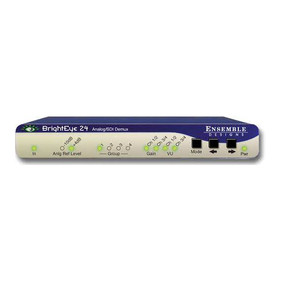
BrightEye 24 OPERATION Control and operation of the BrightEye 24 is performed from the front panel or with the BrightEye PC Control application. Some control settings are only available with BrightEye PC. These parameters cannot NOTE: be monitored or controlled with the front panel. - Page 6 BrightEye 24 SDI to Analog Converter and Disembedder Controls Adjustable parameters are controlled from the front panel using the three push- buttons on the right hand side of the control panel. The control system has the following modes: Idle – all indicators apart from the VU meters are steady-state (no blinking) Analog Ref Level Select –...
- Page 7 If the unit is connected to a computer running the BrightEye PC application, the following menus are available for controlling and monitoring the BrightEye 24 unit. Config Menu • Input Pres – indicates the presence of an SDI input. Shows: None, 525 Lock, or 625 Lock.
- Page 8 BrightEye 24 SDI to Analog Converter and Disembedder Mixer Menu • Outputs 1-4 – provides peak/VU status, with the same methodology as the front panel VU indicators, but on a per channel basis, rather than per channel pair. Peak/VU indicators illuminate red when the audio level on that channel exceeds the headroom level set by the user (with the Peak Indicator control.) Additionally, the VU indicator illuminates orange when...
-
Page 9: Warranty And Factory Service
WARRANTY AND FACTORY SERVICE Warranty Ensemble Designs, Inc. warrants this product to be free from defect in material and workmanship for a period of two years from the date of delivery. During this two year warranty period, Ensemble Designs, Inc. will repair any defective units at Ensemble’s expense if the unit should be determined to be defective after con-... -
Page 10: Specifications
BrightEye 24 SDI to Analog Converter and Disembedder SPECIFICATIONS Video Input: Type: 270 Mb/s Serial Digital (SMPTE 259M) Impedance: 75 Ω Return Loss: > 15 dB to 270 MHz Cable Length: 300 meters Video Output: Number: Type: NTSC or PAL composite... - Page 11 BrightEye 24 GLOSSARY This is a brief glossary of commonly used terms associated with this product. AES/EBU The digital audio standard defined as a joint effort of the Audio Engineering Society and the European Broadcast Union. AES/EBU or AES3 describes a serial bitstream that carries two audio channels, thus an AES stream is a stereo pair.
- Page 12 BrightEye 24 SDI to Analog Converter and Disembedder Component In a component video system, the totality of the image is carried by three separate but related components. This method provides the best image fidelity with the fewest artifacts, but it requires three independent transmission paths (cables).
- Page 13 BrightEye 24 Error Detection and Handling is a method to verify proper reception of an SDI or HD-SDI signal at the destination. The originating device inserts a data packet in the vertical interval of the SDI signal and every line of the HD signal which contains a checksum of the entire video frame.
- Page 14 BrightEye 24 SDI to Analog Converter and Disembedder Interlace Human vision can be fooled to see motion by present a series of images, each with a small change relative to the previous image. In order to eliminate the flicker, our eyes need to see more than 30 images per second. This is accomplished in television systems by dividing the lines that make up each video frame (which run at 25 or 30 frames per second) into two fields.
- Page 15 BrightEye 24 NTSC The color television encoding system used in North America was originally defined by the National Television Standards Committee. This American standard has also been adopted by Canada, Mexico, Japan, Korea, and Taiwan. (This standard is referred to disparagingly as Never Twice Same Color.)
- Page 16 BrightEye 24 SDI to Analog Converter and Disembedder RGB systems carry the totality of the picture information as independent Red, Green, and Blue signals. Television is an additive color system, where all three components add to produce white. Because the luminance (or detail) information is carried partially in each of the RGB channels, all three must be carried at full bandwidth in order to faithfully reproduce an image.
- Page 17 BrightEye 24 Time Base Error Time base error is present when there is excessive jitter or uncertainty in the line to line output timing of a video signal. This is commonly associated with playback from video tape recorders, and is particularly severe with consumer type hetero- dyne systems like VHS.
Need help?
Do you have a question about the BrightEye 24 and is the answer not in the manual?
Questions and answers