Table of Contents
Advertisement
Quick Links
HD/SD/ASI Electrical to
Optical Converter
E
N S E M B L E
D
E
S
I
G
N
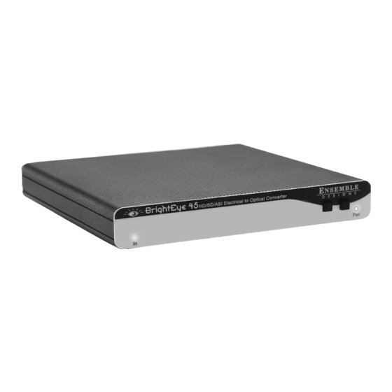
This user guide provides detailed information for using the BrightEye™ 45
HD/SD/ASI Electrical to Optical Converter with distribution amplifier.
The information in this user guide is organized into the following sections:
• Product Overview
• Applications
• Rear Connections
• Operation
• Front Panel Status Indicators
• Warranty and Factory Service
• Specifications
• Glossary
User Guide
S
BrightEye-1
TM
Revision 2.0 SW v1.0.3
Advertisement
Table of Contents

Subscribe to Our Youtube Channel
Summary of Contents for Ensemble Designs BrightEye 45
-
Page 1: User Guide
HD/SD/ASI Electrical to Optical Converter User Guide N S E M B L E Revision 2.0 SW v1.0.3 This user guide provides detailed information for using the BrightEye™ 45 HD/SD/ASI Electrical to Optical Converter with distribution amplifier. The information in this user guide is organized into the following sections: •... -
Page 2: Product Overview
A glossary of commonly used video terms is provided at the end of this guide. Optical Out Laser Diode HD/SD/ASI Out HD/SD/ASI In (follows input) Reclocker Input Signal Power Front Panel Indicators BrightEye 45 Functional Block Diagram BrightEye-2... - Page 3 APPLICATIONS BrightEye 45 can be utilized in any number of different applications where con- version of HD, SD or ASI signals to optical is required. The reclocked electrical input can also be distributed to four electrical output BNCs. As shown in the example below, this unit can accommodate the need to send the input signal optically to a remote location as well as distribute the input to other electrical destinations.The HD, SD, or ASI input can be converted and output...
-
Page 4: Rear Connectors
HD/SD/ASI to Optical Converter REAR CONNECTORS All connections to the BrightEye 45 are made on the rear of the unit. Refer to the illustration below. CAUTION: This is a Class A Laser Product. The optical output emits invisible radiation. Do not stare directly into the optical output beam or view directly with optical instruments. -
Page 5: Operation
OPERATION Monitoring of the BrightEye 45 converter is performed from the front panel as illustrated in the figure below. This is a simple device with no interface to the BrightEye PC Control application.There are no adjustments required for this unit. -
Page 6: Warranty And Factory Service
WARRANTY AND FACTORY SERVICE Warranty Ensemble Designs, Inc. warrants this product to be free from defect in material and workmanship for a period of two years from the date of delivery. During this two year warranty period, Ensemble Designs, Inc. will repair any defective units at Ensemble’s expense if the unit should be determined to be defective after con-... -
Page 7: Specifications
SPECIFICATIONS Serial Digital Input: Number: Signal Type: 270 Mb/s SD Serial Digital (SMPTE 259M) or 1.485 Gb/s HD Serial Digital (SMPTE 274M or 296M) Impedance: 75 Ω Return Loss: > 15 dB Max Cable Length 300 meters for 270 Mb/s 100 meters for 1.485 Gb/s Serial Digital Output: Number:... - Page 8 HD/SD/ASI to Optical Converter GLOSSARY This is a brief glossary of commonly used terms associated with this product. AES/EBU The digital audio standard defined as a joint effort of the Audio Engineering Society and the European Broadcast Union. AES/EBU or AES3 describes a serial bitstream that carries two audio channels, thus an AES stream is a stereo pair.
- Page 9 Chroma The color or chroma content of a signal, consisting of the hue and saturation of the image. See also Color Difference. Component In a component video system, the totality of the image is carried by three separate but related components. This method provides the best image fidelity with the fewest artifacts, but it requires three independent transmission paths (cables).
- Page 10 HD/SD/ASI to Optical Converter dBFS In Digital Audio systems, the largest numerical value that can be represented is referred to as Full Scale. No values or audio levels greater than FS can be repro- duced because they would be clipped. The nominal operating point (roughly corre- sponding to 0 VU) must be set below FS in order to have headroom for audio peaks.
- Page 11 The International Electrotechnical Commission provides a wide range of worldwide standards. They have provided standardization of the AC power con- nection to products by means of an IEC line cord. The connection point uses three flat contact blades in a triangular arrangement, set in a rectangular connector. The IEC specification does not dictate line voltage or frequency.
- Page 12 HD/SD/ASI to Optical Converter Multi-mode Multi-mode fibers have a larger diameter core (either 50 or 62.5 microns), and a correspondingly larger aperture. It is much easier to couple light energy into a multimode fiber, but internal reflections will cause multiple “modes” of the signal to propagate down the fiber.
- Page 13 Return Loss An idealized input or output circuit will exactly match its desired impedance (generally 75 ohms) as a purely resistive element, with no reactive (capacitive or inductive elements). In the real world we can only approach the ideal. So our real inputs and outputs will have some capacitance and inductance.
- Page 14 HD/SD/ASI to Optical Converter A Time Base Corrector is a system to reduce the Time Base Error in a signal to acceptable levels. It accomplishes this by using a FIFO (First In, First Out) memory. The incoming video is written into the memory using its own jittery timing.


Need help?
Do you have a question about the BrightEye 45 and is the answer not in the manual?
Questions and answers