Table of Contents
Advertisement
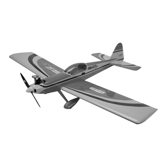
Pulse XT 60 ARF
Specifications
Wingspan ....................................... 70 in (1778mm)
Wing Area .......................... 885 sq in (5710 sq cm)
Length ......................................... 57.3 in (1455mm)
Weight ............................. 7–8 lb (3.18 kg–3.63 kg)
Assembly mAnuAl
Engine ................................... .91–1.00 Four-Stroke
....................................... .60–.75 Two-Stroke
...........................................Power 60 Electric
Radio..............4-Channel w/5 Servos (4 for electric)
Advertisement
Table of Contents

Related Manuals for Hangar 9 Pulse XT 60 ARF


Summary of Contents for Hangar 9 Pulse XT 60 ARF
- Page 1 Pulse XT 60 ARF Assembly mAnuAl Specifications Wingspan ........70 in (1778mm) Engine ........91–1.00 Four-Stroke Wing Area ......885 sq in (5710 sq cm) ........60–.75 Two-Stroke Length ......... 57.3 in (1455mm) ...........Power 60 Electric Weight ......7–8 lb (3.18 kg–3.63 kg)
-
Page 2: Table Of Contents
Table of Contents Using the Manual ..............3 Required Tools and Adhesives . -
Page 3: Using The Manual
Using the Manual This manual is divided into sections to help make assembly easier to understand, and to provide breaks between each major section. In addition, check boxes have been placed next to each step to keep track of each step completed. Steps ... -
Page 4: Radio And Power Systems Requirements
Radio and Power Systems Requirements • 4-channel radio system (minimum) w/receiver • 1500mAh Ni-MH 4-cell (JSP91030) • JR Standard Switch (JSP98010) or JR Chargeswitch (JRPA004) • DS821 Digital Sport Servo (JRPS821) (5) or equivalent (4 when building electric version) • In-line fuel filter (DUB340) •... -
Page 5: Recommended Setup-2-Stroke Glow
Recommended Setup–2-Stroke Glow • Evolution ® .61NT with Muffler (EVOE0610) • Evolution Propeller: 11 x 7, 12 x 6 (EVO11070, EVO12060)) Evolution .61NT EVOE0610 Recommended Setup–4-Stroke Glow • Saito ™ 1.00 AAC w/Muffler (SAIE100 or SAIE100GK) • Evolution Propeller: 14 x 8 (EVO14080) Saito 1.00 AAC SAIE100 Recommended Setup–Electric... -
Page 6: Warranty Information
Warranty Information Warranty Period Exclusive Warranty- Horizon Hobby, Inc., (Horizon) warranties that the Products purchased (the "Product") will be free from defects in materials and workmanship at the date of purchase by the Purchaser. Limited Warranty (a) This warranty is limited to the original Purchaser ("Purchaser") and is not transferable. REPAIR OR REPLACEMENT AS PROVIDED UNDER THIS WARRANTY IS THE EXCLUSIVE REMEDY OF THE PURCHASER. -
Page 7: Inspection Or Repairs
Questions, Assistance, and Repairs Your local hobby store and/or place of purchase cannot provide warranty support or repair. Once assembly, setup or use of the Product has been started, you must contact Horizon directly. This will enable Horizon to better answer your questions and service you in the event that you may need any assistance. -
Page 8: Contents Of Kit / Replacement Parts
Safety, Precautions, and Warnings This model is controlled by a radio signal that is subject to interference from many sources outside your control. This interference can cause momentary loss of control so it is advisable to always keep a safe distance in all directions around your model, as this margin will help to avoid collisions or injury. -
Page 9: Section 1: Aileron Servo Installation
Section 1: Aileron Servo Installation Required Parts Step 2 • Wing panel w/ailerons (right and left) Flex each aileron up and down a number of times to • Servo w/hardware (2) break in the hinges. • 6 -inch (89mm) aileron linkage (2) Required Tools and Adhesives •... - Page 10 Section 1: Aileron Servo Installation Step 3 Step 5 Prepare the aileron servo by installing the grommets and Use a 5/64-inch (2mm) drill bit to enlarge the outer hole brass eyelets provided with the servo. Plug the aileron of the servo arm.
- Page 11 Section 1: Aileron Servo Installation Step 7 Step 9 Repeat Steps 3 through 7 to prepare a second aileron After cutting the threads into the wood, apply a few servo. Note the direction of the servo arm in relationship drops of thin CA to each of the four holes to harden the to the servo.
- Page 12 Section 1: Aileron Servo Installation Step 10 Step 11 Tie a wheel collar to the end of a 12-inch (300mm) piece Tie the string that exits the servo opening to the servo of string. Lower the wheel collar into the opening for the extension.
- Page 13 Section 1: Aileron Servo Installation Step 12 Step 14 Secure the servo using the screws provided with Attach the clevis to the center hole on the servo horn. the servo. The servo is positioned so the output of the servo faces the aileron, and the servo arm will face toward the wing tip.
- Page 14 Section 1: Aileron Servo Installation Step 16 Step 18 Use pliers to make a 90-degree bend at the mark made in Use side cutters to trim the pushrod wire so only the previous step. 1/16-inch (1.5mm) extends beyond the connector. ...
-
Page 15: Section 2: Landing Gear Installation
Section 2: Landing Gear Installation Required Parts o Step 2 • Fuselage assembly • Landing gear Use two adjustable wrenches to attach the axles to the • Wheel pant (left and right) • Axle w/nut (2) landing gear. • 5/32-inch wheel collar w/setscrew (4) •... - Page 16 Section 2: Landing Gear Installation Step 4 Step 6 Secure one of the 5/32-inch wheel collars to the axle Slide the wheel pant over the axle and wheel. Use a near the gear using a setscrew and the supplied hex 4-40 x 1/2-inch socket head screw and a #4 washer wrench.
- Page 17 Section 2: Landing Gear Installation Step 9 The tail wheel follows the same procedure as the main wheels, except no wheel pant is involved. The two wheel collars used to secure the tail wheel are 1/16-inch. Note: Use threadlock on the setscrews to prevent them from vibrating loose in flight.
-
Page 18: Section 3: Rudder And Elevator Installation
Section 3: Rudder and Elevator Installation Required Parts Step 3 • Fuselage assembly • Servo (2) Slide the threaded studs from the fin into the holes in • 180-degree servo horn (2) the stabilizer. The studs will then go through the holes in the fuselage. - Page 19 Section 3: Rudder and Elevator Installation Step 5 Step 7 Thread one of the servo mounting screws into each of Prepare the rudder servo by installing the grommets and the pre-drilled holes for the rudder and elevator servos brass eyelets provided with the servo.
- Page 20 Section 3: Rudder and Elevator Installation Step 8 Step 10 Use side cutters to remove one of the arms from the Repeat Steps 7 through 9 to prepare the elevator servo. servo horn. Note the direction of the servo arm in relationship to the rudder servo.
- Page 21 Section 3: Rudder and Elevator Installation Step 12 Step 14 Use low-tack tape to secure the elevators and rudder in Slide the pushrod into the hole on the right side of the the neutral position at this time. fuselage.
- Page 22 Section 3: Rudder and Elevator Installation Step 16 Step 18 Center the rudder servo using the radio system. Use a Secure the pushrod wire to the servo horn using a felt-tipped pen to mark the pushrod where it crosses the pushrod connector.
- Page 23 Section 3: Rudder and Elevator Installation Step 20 Step 21 Slide the pushrod into the hole on the left side of the Attach the clevis to the center hole of the control horn. fuselage. Step 22 Repeat Steps 17 through 20 to install the elevator linkage as shown in the photo.
-
Page 24: Section 4: Glow Engine And Cowling Installation
Section 4: Glow Engine and Cowling Installation Required Parts Step 2 • Fuselage assembly • Fuel tank Position the engine on the engine mounting rails so • 19 -inch throttle pushrod • Cowling the drive washer is 5 -inch (146mm) forward of the firewall as shown. - Page 25 Section 4: Glow Engine and Cowling Installation Step 4 Step 6 Dill the locations for the engine mounting screws using a Use a 5/64-inch (2mm) drill bit to enlarge the outer hole drill and 11/64-inch (4.5mm) drill bit. in the carburetor arm.
- Page 26 Section 4: Glow Engine and Cowling Installation Special Steps for 4-Stroke Installation Step 3 The following steps are required to provide clearance Remove the carburetor arm from the carburetor. Use a between the carburetor arm and engine mounting rail. 5/64-inch (2mm) drill bit to enlarge the outer hole in the carburetor arm.
- Page 27 Section 4: Glow Engine and Cowling Installation Step 9 Step 10b Slide the throttle pushrod into the pushrod tube on the Slide the connector (and carburetor arm) onto the same side of the fuselage as the carburetor arm. throttle pushrod.
- Page 28 Section 4: Glow Engine and Cowling Installation Step 12 Step 14 Look carefully at the fuel tank to determine which tubes Use a 5/64-inch (2mm) drill bit and pin drill to enlarge the are for the carburetor and vent. Also check the direction outer hole of a standard servo arm as shown.
- Page 29 Section 4: Glow Engine and Cowling Installation Step 16 Step 18 Plug the throttle servo into the receiver. Center the throttle With the throttle stick and trim centered, open the stick and trim at the transmitter. With the throttle servo carburetor to the mid-throttle position.
- Page 30 Section 4: Glow Engine and Cowling Installation Step 20 Step 22 Use side cutters to remove the excess pushrod wire that Slide the cowling onto the fuselage. Use four 4-40 x could interfere with the operation of your engine. 3/8-inch socket head screws and four #4 washers to secure the cowling to the fuselage.
- Page 31 Section 4: Glow Engine and Cowling Installation Step 24 Step 25 Install the engine back onto the engine mount. Slide the Slide the spinner backplate onto the propeller shaft. cowling over the engine, trimming the cowl as necessary to fit over the engine and provide clearance for items such as the needle valve and muffler.
- Page 32 Section 4: Glow Engine and Cowling Installation Step 27 Step 28 Use a #1 Phillips screwdriver and the screws Attach the muffler as instructed in the manual for your supplied with the spinner to secure the spinner cone particular engine.
-
Page 33: Section 5: Electric Motor And Cowling Installation
Section 4: Glow Engine and Cowling Installation Note: We install a Dubro inline fuel filter (DUB340) between the fuel tank and carburetor. Section 5: Electric Motor and Cowling Installation Required Parts Step 1 • Fuselage assembly • Plywood battery tray Use a hobby knife to remove the plywood from the •... - Page 34 Section 5: Electric Motor and Cowling Installation Step 2 Step 4 Route the two longer hook and loop straps through the Slide the battery tray into the fuselage with the ESC slots inside the fuselage. facing toward the bottom of the fuselage. Secure the battery tray in the fuselage using two #4 x 3/8-inch sheet metal screws.
- Page 35 Section 5: Electric Motor and Cowling Installation Step 6 Step 8 Attach the X-mount to the motor using the screws Secure the motor battery inside the fuselage using the provided with the motor. hook and loop straps. Note: Use threadlock on the screws to Note: If the battery slides on the tray, it may prevent them from vibrating loose in flight.
-
Page 36: Slide The Cowling Onto The Fuselage. Use Four 4-40 X
Section 5: Electric Motor and Cowling Installation Step 9 Step 11 Slide the cowling onto the fuselage. Use four 4-40 x Slide the propeller into position, aligning it with the pins 3/8-inch socket head screws and four #4 washers to on the spinner back plate. -
Page 37: Section 6: Receiver Installation
Section 6: Receiver Installation Required Parts Step 3 • Fuselage assembly • Switch Secure the receiver as shown using a hook and loop • Receiver • Receiver battery strap. When using a remote receiver, attach the receiver as described in the instructions provided with your radio •... -
Page 38: Section 7: Canopy And Wing Installation
Section 7: Canopy and Wing Installation Required Parts Step 2 • Fuselage assembly • Canopy Use medium sandpaper to scuff the fuselage and canopy • Wing panel (right and left) • Wing dowel (2) where they contact each other. Use rubbing alcohol and a paper towel to remove any debris from the gluing area. - Page 39 Section 7: Canopy and Wing Installation Step 4 Step 6 Use 30-minute epoxy to glue the wooden dowel into Install the 1 -inch x 3/16-inch (81mm x 4.75mm) the hole in he leading edge of the wing. Leave 1/2-inch aluminum anti-rotation pin in the hole near the trailing (13mm) of the dowel protruding from the wing as shown.
- Page 40 Section 7: Canopy and Wing Installation Step 8 Step 9 Connect the extensions (or Y-harness) from the receiver to Attach the wing to the fuselage using two 1/4-20 x 2-inch the aileron servos. nylon wing bolts and the plywood wing bolt plate.
-
Page 41: Section 8: Control Throws
Section 8: Control Throws The amount of control throw should be adjusted as closely Note: All control throws are measured at as possible using mechanical means, rather than making the widest point of the control surface. large changes electronically at the radio. By moving the position of the clevis at the control horn toward the outermost hole, you will decrease the amount of control throw of the control surface. -
Page 42: Section 9: Recommended Center Of Gravity (Cg)
Section 9: Recommended Center of Gravity (CG) An important part of preparing the aircraft for flight is Step 2 properly balancing the model. This is especially important When balancing a low-wing aircraft, it is best to balance it when various engines are mounted. inverted as shown in the drawing below. -
Page 43: Section 10: Pre-Flight
Section 10: Pre-Flight Charge both the transmitter and receiver pack for your Check the radio installation and make sure all the airplane. Use the recommended charger supplied with control surfaces are moving correctly (i.e. the correct your particular radio system, following the instructions direction and with the recommended throws). -
Page 44: 2008 Official Ama National Model Aircraft Safety Code
2008 Official AMA National Model Aircraft Safety Code 8. I will not operate model aircraft carrying pyrotechnic GENERAL devices which explode burn, or propel a projectile 1. A model aircraft shall be defined as a non-human- of any kind. Exceptions include Free Flight fuses or carrying device capable of sustained flight in the devices that burn producing smoke and are securely atmosphere. - Page 45 2008 Official AMA National Model Aircraft Safety Code Radio Control 7. With the exception of events flown under official AMA rules, no powered model may be flown outdoors closer 1. All model flying shall be conducted in a manner to than 25 feet to any individual, except for the pilot and avoid over flight of unprotected people.
- Page 46 Building and Flying Notes...
- Page 47 Building and Flying Notes...
- Page 48 © 2008 Horizon Hobby, Inc. 4105 Fieldstone Road Champaign, Illinois 61822 (877) 504-0233 horizonhobby.com 12603...
Need help?
Do you have a question about the Pulse XT 60 ARF and is the answer not in the manual?
Questions and answers