Table of Contents
Advertisement
Installation and
Operating Manual
H
O – fireplace inserts
2
Mini Z1 H
Mini Z1/Z1h H
Varia 1V/1Vh H
Varia 1V/1Vh H
Varia 1V/1Vh H
Varia 2Lh/2Rh H
Varia Ah H
Varia A-FDh H
Note:
Failure to comply with the instructions contained in the installation and
operating manual will invalidate the warranty.
Where details contained in the supplementary assembly manual differ
from the details in the installation manual, such details should only be
taken into consideration if they impose more stringent requirements.
- We reserve the right to make technical
modifications and accept no liability for
any errors - Issued 01/2014
SPARTHERM
Feuerungstechnik GmbH
Maschweg 38
D - 49324 Melle
O
2
O XL
2
O
2
O XL
2
O XXL
2
O
2
O
2
O
2
Foreword / Our philosophy with regard to
quality
You have decided to purchase a Spartherm product – we would like to
thank you for placing your confidence in us.
In a world characterised by excess and mass production, the good name
of our firm is inextricably linked to the credo of our owner, Gerhard
Manfred Rokossa:
"High technical quality combined with modern design and on-site
customer service carried out to the latter's full satisfaction, in the
expectation that the customer will then recommend us to others."
To you and our partners in specialist dealerships, we offer first-class
products that stir the emotions, appealing to that sense of security and
comfort that we all feel. However, to ensure that we succeed in this, we
recommend that you read the operating manual carefully to quickly
familiarise yourself with your fireplace insert in all its details. In addition to
information on how to use it, this manual also contains important
maintenance and operating instructions for your safety and to ensure your
fireplace insert retains its value.
It also contains valuable tips and advice to help you. In addition, we show
you how to use your product in a way that will protect the environment..
If you have any further questions please contact your dealer.
A beautiful fire at all times.
Your Spartherm team
G.M. Rokossa
- 2 -
Advertisement
Table of Contents

Subscribe to Our Youtube Channel
Related Manuals for Spartherm Mini Z1 H2O


Summary of Contents for Spartherm Mini Z1 H2O
- Page 1 Foreword / Our philosophy with regard to quality Operating Manual You have decided to purchase a Spartherm product – we would like to thank you for placing your confidence in us. In a world characterised by excess and mass production, the good name O –...
-
Page 2: Table Of Contents
Contents Page Foreword / Our philosophy with regard to quality 1. General information 1.1. Scope of supply 1.2. Specification 2. Installation 2.1. Basic installation requirements 2.2. Electrical connection 2.3. H O fireplace insert connections 2.4. Minimum crosssections for convection air 2.5. -
Page 3: General Information
The fireplace may only be used with suitable combustion control systems your chimney and will carry out the acceptance test on your fireplace adjusted as appropriate. Please consult Spartherm Feuerungstechnik insert. The chimney calculation is based on DIN EN 13384 using the value GmbH as necessary. -
Page 4: Specification
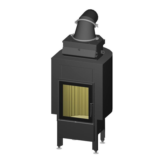
1.2. Specification Weight (empty, without accessories) permissible 14,8 10,3 working Nominal output – – – – – – – – overpressure range 14,3 18,7 27,5 13,5 13,5 Max. permissible Nominal heat feed tempera- °C 11,0 14,4 21,2 14,7 10,4 10,4 output 10,0 ture... - Page 5 Mini Z1 H Fig. 1a Mini Z1 H O XL Fig. 1b - 9 - - 10 -...
- Page 6 Varia 1V H Fig. 1d Mini Z1h H O XL Fig. 1c - 11 - - 12 -...
- Page 7 Varia 1Vh H Fig. 1e Varia 1V H O XL Fig. 1f - 13 - - 14 -...
- Page 8 Varia 1V H O XXL Fig. 1h Varia 1Vh H O XL Fig. 1g - 15 - - 16 -...
- Page 9 Varia 1Vh H O XXL Fig. 1i Varia 2Lh / 2Rh H Fig. 1j - 17 - - 18 -...
- Page 10 Varia Ah H Fig. 1k Varia A-FDh H Fig. 1l Abgaskuppel separater Verbrennungsluftstutzen Ø 150 mm Luftstellhebel Tür klappbar Tür hochschiebbar - 19 - - 20 -...
-
Page 11: Installation
Heat insulating material thicknesses (according to AGI-Q 132). 2. Installation Mounting wall Base Ceiling (side / rear) Generally speaking, the water-heating components and the requisite Mini Z1 H safety devices, etc., must be installed by a specialist company. The Mini Z1 H O XL and 70 mm 103 mm... -
Page 12: Electrical Connection
2.2. Electrical connection During installation, connection and operation of the H O fireplace insert, always follow and apply all the requisite national and European Full electrical installation of the individual components of the heating standards and local regulations (DIN, DIN EN, regional building system may only be carried out by an authorised specialist company. - Page 13 Mini Z1 H O, Mini Z1 H O XL, Mini Z1h H O XL Varia 1V H Varia 1Vh H An inspection opening in the To facilitate access to the water connections of the Varia 1V H O, an rear wall can be opened for inspection opening in the rear wall can be opened.
- Page 14 Varia 1V H O XL, Varia 1Vh H O XL, Varia 2Lh/2Rh H Varia 1V H O XXL, Varia 1Vh H O XXL For access to the water For access to the water connections of the Varia connections of the Varia 1V 2Lh/2Rh H O an inspection inspection...
- Page 15 Varia Ah H O und Varia A-FDh H For access to the water connections of the Varia Ah H2O / A-FDh H2O an opening has to be made in the fireplace cover. The deflector plate must rest against the side wall of the combustion chamber (see Fig. 2e). Deflector plate (optional)
-
Page 16: Minimum Crosssections For Convection Air
be removed during installation and replaced by suitable, permanent- 2.4. Minimum crosssections for convection air ly tight plugs. The connections are clearly marked and must not be used for any other purpose. The integral safety device (safety heat exchanger) The minimum cross-sections for the convection air (supply air and must not be used to heat water. -
Page 17: Safety Valve
For this version the following additional information must be borne in mind 2.6. Safety valve when performing installation. A component-tested safety valve (e.g., Syr type 1915), with a maximum TROL guidelines response overpressure of 3.0 bar must be installed in the feed pipe in regarding the free cross- the immediate vicinity of the H O fireplace insert. -
Page 18: Overheat Discharge Valve
2.8. Overheat discharge valve 2.9. Thermal pump control system Since the heating for the H O fireplace insert is not automatic and cannot The fireplace insert must always be used with a load unit. A JUMO or be quickly switched off, the hot water attachment must be equipped with Afriso thermostat switch is also supplied with the cell. -
Page 19: Incorporation Into A Heating System
The connection is made as shown in Fig. 4a and 4b. The blue wire is the connected phase (L`) and is phase wired to the circulating pump or load unit. The green-and-yellow wire is wired to the protective conductor (earth) (PE) of the mains supply. The brown wire is wired to phase (L) of the mains supply. - Page 20 For the Mini Z1 H The following assumptions were made in this case: Buffer storage tank size: 300 litres (approx. 300 kg of water) Water temperature in the storage tank initially: 30°C Final water temperature in the storage tank: 60°C ...
- Page 21 Possible variant for incorporating the Mini Z1 H O, Mini Z1 H O XL and Mini Z1h H O XL into a heating system (Fig. 5a). temperature sensor for the ½“ overheat discharge valve temperature sensor for the ½“ thermostat switch ¾“...
- Page 22 Possible variant for incorporating the Varia 1V H O and Varia 1Vh H O in a heating system (Fig. 5b). 3/8“ bleed valve temperature sensor for the ½” overheat discharge valve temperature sensor for the ½” thermostat switch safety valve - 3 bar return pump thermostat switch (eg.
- Page 23 Possible variant for incorporating the Varia 1V H O XL, Varia 1Vh H O XL, Varia 1V H O XXL and Varia 1Vh H O XXL into a heating system (Fig. 5c). temperature sensor for the ½“ overheat discharge valve temperature sensor for the ½”...
- Page 24 Possible variant for incorporating the Varia 2Lh / 2Rh H O into a heating system ¾” feed temperature sensor for the ½” overheat discharge valve temperature sensor for the ½” thermostat switch ¾” return discharge from ½” overheat discharge valve supply to ½”...
- Page 25 Possible variant for incorporating the Varia Ah H O into a heating system (Fig. 5e). ¾” feed ¾” return temperature sensor for the ½” overheat discharge valve temperature sensor for the ½” overheat discharge valve Thermal safety heat exchanger ½” ‘discharge’ Thermal safety heat exchanger ½”...
- Page 26 Possible variant for incorporating the Varia A-FDh H O into a heating system (Fig. 5f). ¾” feed ¾” return temperature sensor for the ½” overheat discharge valve temperature sensor for the ½” overheat discharge valve Thermal safety heat exchanger ½” ‘discharge’ Thermal safety heat exchanger ½”...
-
Page 27: Chimney Connection / Connecting Piece
3. Pull off the door 2.11. Chimney connection / connecting piece stops in the direc- tion of the red ar- The H O fireplace insert is connected to the chimney by means of row. The stop may connecting pieces of sheet steel approx. 2 mm thick. These must conform have become to DIN 1298 or DIN EN 28160 or the country-specific regulations... -
Page 28: Initial Commissioning
O fireplace insert. Further instructions on operating the H O fireplace insert are given in the enclosed operating manual for Spartherm fireplace inserts. The H O fireplace insert/heating systems must be filled and bled before being lit. The heating system pressure must be checked (~ 1.5 bar) at the same time. -
Page 29: Operation
O fireplace insert should be lit and stoked as evenly as possible and the fire should not be allowed to subside to embers too often Risk of oxygen corrosion: Constant presence of air in the fireplace insert is due to a leak in the if uniform heat discharge from the heat exchanger is to be en- customer’s upstream pipework or incorrect positioning/dimensioning of the sured and low chimney temperatures avoided. -
Page 30: Cleaning And Maintenance
5. Cleaning and maintenance For cleaning, please also refer to the notes in the operating manual for the fireplace insert. The notes in this installation and operating manual relate only to the cleaning of the heat exchanger of the H O fireplace insert. -
Page 31: Cleaning The Double Glazing
on the side where the glass is. 6. Troubleshooting Note: The fireplace must not be used as a waste incinerator. Furthermore 5.2. Cleaning the double glazing it is intended for non-continuous use. Nor can continuous combustion be achieved by extracting combustion air – attempting to do this is not permitted. -
Page 32: General Warranty Terms And Conditions
These General Warranty Terms and Conditions apply to the relationship Check the heat circulating pump for between the manufacturer, Spartherm Feuerungstechnik GmbH, and the dealer/intermediary. They are not the same as the contract and warranty correct operation. -
Page 33: Warranty Exclusions
In accordance with this warranty undertaking Spartherm Feuerungstech- nik GmbH reserves the right either to rectify the defect or to replace the If such proof is not produced Spartherm Feuerungstechnik GmbH shall unit free of charge. Remediation of defects shall take preceden. This not be obliged to honour the warranty. -
Page 34: Note
7.10 Note 9. Commissioning log Your specialist dealer/contractor will gladly advise and assist you in matters not covered by our warranty terms and conditions and undertak- Unit no.: ings. We particularly advise you to have your fireplace insert/ Date:_________________________ (see name plate) stove serviced regularly by a stove fitter.
Need help?
Do you have a question about the Mini Z1 H2O and is the answer not in the manual?
Questions and answers