Table of Contents
Advertisement
Advertisement
Table of Contents

Related Manuals for Motorola AP-8132


Summary of Contents for Motorola AP-8132
- Page 1 AP-8132 Access Point INSTALLATION GUIDE...
- Page 2 AP-8132 Access Point MOTOROLA SOLUTIONS and the Stylized M Logo are registered in the US Patent & Trademark Office. © Motorola Solutions, Inc. 2013. All rights reserved.
-
Page 3: Table Of Contents
1.3 Site Preparation ......... . . 6 1.4 AP-8132 Package Contents ........6 1.4.1 Features . - Page 4 5.13 Turkish WEEE Statement of Compliance ..... .43 6.0 Motorola Solutions Support Center ......44...
-
Page 5: Introduction
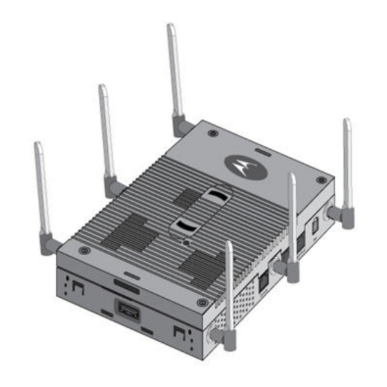
Installation Guide Introduction The AP-8132 is a premium, Enterprise class, Access Point positioned at the top of Motorola Solutions’ Access Point product line. The AP-8132 is a plenum rated, 3x3:3 802.11n Access Point utilizing two 802.11abgn radios. An AP-8132 model Access Point uses WiNG 5 software as its onboard operating system. The Access Point’s... -
Page 6: Warnings
• Verify cable lengths are within the maximum allowable distances for optimal signal transmission. 1.4 AP-8132 Package Contents An AP-8132 Access Point is available in external antenna models only. An AP-8132 ships with the following: • AP-8132 access point • AP-8132 Installation Guide (This Guide) •... -
Page 7: Features
• Features for snap-on module support through the Access Point’s USB interface • 3x3 MIMO, 3 spatial streams The AP-8132 access point has two RJ-45 connectors supporting 10/100/1000 Ethernet. GE1/POE accepts 802.3at or 802.3af compliant power from an external source... -
Page 8: Hardware Installation
Hardware Installation 2.1 Installation Instructions An AP-8132 Access Point mounts either on a wall (with M4 x 25 pan head screws and wall anchor - or equivalent) or on a suspended ceiling T-bar. Once the AP-8132 is installed with facade and cabled, the cables (Ethernet and module connections) should not be visible when looking directly at the unit (ceiling and wall mounts). -
Page 9: Access Point Placement
2.4 Power Injector System An AP-8132 model Access Point can receive power via an Ethernet cable connected to the GE1/POE (LAN) port. When users purchase a WLAN solution, they often need to place Access Points in obscure locations. In the past, a dedicated power source was required for each Access Point in addition to the Ethernet infrastructure. - Page 10 Access Point and void the product warranty. A separate Power Injector is required for each AP-8132 Access Point comprising the network. The Power Injector can be installed free standing, on an even horizontal surface or wall mounted using the power injector’s wall mounting key holes.
-
Page 11: Wall Mount Instructions
A wall mount deployment requires hanging the AP-8132 access point along its width or length using two of three slots on the bottom of the unit. The AP-8132 can be mounted on to any plaster, wood or cement wall surface using the provided wall anchors. -
Page 12: Wall Mount Procedure - New Installation
• Philips head screw driver, or drill and drill bit 2.5.1 Wall Mount Procedure - New Installation This section describes a new AP-8132 installation with no previous Access Point existing on the intended wall surface. 1. Place the Access Point against the wall, ensuring the Access Point’s Motorola Solutions “bat wings” logo is in the correct orientation. -
Page 13: Wall Mount Procedure - Existing Access Point Replacement
2.6 Suspended Ceiling T-Bar Mount Instructions Ceiling mount requires holding the AP-8132 up against a T-bar of a suspended ceiling grid and twisting the unit on to the T-bar. If deploying the AP-8132 on a sculpted ceiling T-Bar, the Access Point mounting kit (Part No. - Page 14 Do not actually connect to the power source until the cabling portion of the installation is complete. 5. Verify the unit has power by observing the LEDs. For more information on AP-8132 LED behavior, see LED Indicators on page 20 6.
-
Page 15: Suspended Ceiling Tile (Plenum) Installation
Notes or warnings about suspended ceiling mounts apply to all NOTE installations where the unit is placed on suspended ceiling tile. Motorola does not recommend mounting the Access Point directly to CAUTION any suspended ceiling tile with a thickness less than 12.7mm (0.5in.) or a suspended ceiling tile with an unsupported span greater than 660mm (26in.). - Page 16 9. Fit the light pipe into hole in the tile from its unfinished side. 10. Slide the badge onto the light pipe from the finished side of the ceiling tile. 11. Attach the antennas to their correct connectors. For more information on supported AP-8132 antennas, AP-8132 Antenna Options on page 18...
- Page 17 Do not actually connect to the power source until the cabling portion of the installation is complete. 14. Verify the behavior of the Access Point LED light pipe. For more information on AP-8132 LED behavior, see LED Indicators on page 20 15.
-
Page 18: Ap-8132 Antenna Options
AP-8132 Access Point 2.8 AP-8132 Antenna Options Motorola Solutions supports two antenna suites for an AP-8132. One antenna suite supporting the 2.4 GHz band and another antenna suite supporting the 5 GHz band. Select an antenna model best suited to the intended operational environment of the AP-8132 Access Point. - Page 19 The Access Point also supports a plastic facade (cover), separately ordered, that either contains an antenna (Part No. ML-2452-PTA6M6-1) or serves as a plastic cover without an antenna (Part No. 21-8132FAC-01) For up-to-date information on supported antennas and antenna specifications, please refer to the Motorola Solutions Enterprise Wireless LAN Antenna Specification Guide available at...
-
Page 20: Led Indicators
AP-8132 Access Point 2.9 LED Indicators Both Integrated Antenna and External Antenna models have LED activity indicators on the front of the case. With the External Antenna models mounted above a ceiling, LEDs are at the center of an oval badge on the ceiling. - Page 21 Installation Guide Task 5 GHz Activity LED (Amber) 2.4 GHz Activity LED (Green) Firmware Update Locate AP LEDs blink in an alternating green, red and LEDs blink in an alternating green, red and Mode amber pattern using an irregular blink rate. amber pattern using an irregular blink rate.
-
Page 22: Basic Access Point Configuration
AP-8132 Access Point Basic Access Point Configuration Once the Access Point is installed and powered on, complete the following steps to get the Access Point up and running and access management functions: 1. The Access Point’s IP address is optimally provided using DHCP. A zero config IP address can also be derived if DHCP resources are unavailable. - Page 23 Installation Guide 3. Enter the default username admin in the Username field. 4. Enter the default password motorola in the Password field. 5. Click the Login button to load the management interface. When logging in for the first time, you’re prompted to change the NOTE password to enhance device security in subsequent logins.
- Page 24 AP-8132 Access Point The Initial Setup Wizard displays the same pages and content for each NOTE Access Point model supported. The only difference being the number of radios configurable by model, as an AP7131 model can support up to three radios, AP6522, AP6532, AP6562, AP8132 and AP7161 models support two radios and AP6511 and AP6521 models support a single radio.
- Page 25 Installation Guide 7. Select Save/Commit within each page to save the updates made to that page's configuration. Select Next to proceed to the next page listed in the Navigation Panel without saving your updates. While you can navigate to any page in the navigation panel, you cannot NOTE complete the Initial AP Setup Wizard until each task in the Navigation Panel has a green checkmark.
- Page 26 UI to connect to the Access Point, provision its configuration and administrate the Access Point’s configuration. If designating the Access Point as a Standalone AP, Motorola Solutions NOTE recommends the Access Point’s UI be used exclusively to define its device configuration, and not the CLI.
- Page 27 Installation Guide 13. The Typical Setup Wizard displays the Network Topology screen to define how the Access Point handles network traffic. 14. Select an Access Point Mode from the available options. • Router Mode -In Router Mode, the Access Point routes traffic between the local network (LAN) and the Internet or external network (WAN).
- Page 28 AP-8132 Access Point 15. Select Next. The Typical Setup Wizard displays the LAN Configuration screen to set the Access Point's LAN interface configuration. 16. Set the following DHCP and Static IP Address/Subnet information for the LAN interface: • Use DHCP - Select the checkbox to enable an automatic network address configuration using the Access Point’s DHCP server.
- Page 29 Installation Guide • DNS Forwarding - Select this option to allow a DNS server to translate domain names into IP addresses. If this option is not selected, a primary and secondary DNS resource must be specified. DNS forwarding is useful when a request for a domain name is made but the DNS server, responsible for converting the name into its corresponding IP address, cannot locate the matching IP address.
- Page 30 AP-8132 Access Point 19. Select Next. The Typical Setup Wizard displays the RADIUS Server Configuration screen if required. Otherwise, the Typical Setup Wizard displays the Summary and Commit screen. 20. Use the Radius Server Configuration screen to configure the users for the onboard RADIUS server. Use...
- Page 31 Installation Guide 21. Select Add User to display the dialog to enter user information to add to the RADIUS server user database. 22. Enter the following user information: • Username - Provide a user name used to authenticate the user. •...
- Page 32 AP-8132 Access Point 28. Select Next. The Typical Setup Wizard displays the Summary and Commit screen to summarize the screens (pages) and settings updated using the Typical Setup Wizard. No user intervention or additional settings are required. Its an additional means of validating the Access Point’s updated configuration before it’s deployed.
-
Page 33: Specifications
Installation Guide Specifications 4.1 Electrical Characteristics An AP-8132 model Access Point has the following electrical characteristics: Operating Current & 48VDC, 0.625A (AUX input voltage) Voltage 48VDC, 0.75A (PWRS-14000-247R power supply) 802.3at, 25.5W (AP-PSBIAS-2P3-ATR Power Injector) 4.2 Physical Characteristics An AP-8132 model Access Point has the following physical characteristics: Dimensions 9 inches x 6.00 inches x 1.75 inches... -
Page 34: Radio Characteristics
AP-8132 Access Point 4.3 Radio Characteristics The AP-8132 model Access Point has the following radio characteristics: Data Rates Supported 802.11b: 1,2,5.5,11Mbps 802.11g: 1,2,5.5,11,6,9,12,18,24,36,48, and 54Mbps 802.11a: 6,9,12,18,24,36,48, and 54Mbps 802.11n: MCS 0-23 up to 450Mbps Wireless Medium Direct Sequence Spread Spectrum (DSSS),... -
Page 35: Regulatory Information
This device is approved under Motorola Solutions, Inc. This guide applies to the following Model Numbers: AP-8132. All Motorola/Symbol devices are designed to be compliant with rules and regulations in locations they are sold and will be labeled as required. -
Page 36: Health And Safety Precautions
AP-8132 Access Point Industry Canada Statement: Caution: The device for the band 5150-5250 MHz is only for indoor usage to reduce potential for harmful interference to co-Channel mobile satellite systems. High power radars are allocated as primary users (meaning they have priority) of 5250-5350 MHz and 5650-5850 MHz and these radars could cause interference and/or damage to LE-LAN devices. -
Page 37: Rf Exposure Giudelines
This device must be powered from a 802.3af or 802.3at compliant power source which has been certified by the appropriate agencies, or by a LISTED Motorola, Type no. PWRS-14000-247R or AP-PSBIAS-2P3-ATR, direct plug-in power supply, marked Class 2 or LPS (IEC60950-1,... -
Page 38: Radio Frequency Interference Requirements-Fcc
AP-8132 Access Point 5.8 Radio Frequency Interference Requirements—FCC This equipment has been tested and found to comply with the limits for a Class B digital device, pursuant to Part 15 of the FCC rules. These limits are designed to provide reasonable protection against harmful interference in a residential installation. -
Page 39: Ce Marking And European Economic Area
Refer to section 2.8 of this guide for a listing of the 2.4 and 5 GHz antennas initially approved for use with the AP-8132. 5.10 CE Marking and European Economic Area (EEA) The use of 2.4GHz RLAN’s, for use through the EEA, have the following restrictions:... - Page 40 Declarações Regulamentares para AP-8132 - Brasil Nota: A marca de certificação se aplica ao Transceptor, modelo AP-8132. Este equipamento opera em caráter secundário, isto é, não tem direito a proteção contra interferência prejudicial, mesmo de estações do mesmo tipo, e não pode causar interferência a sistemas operando em caráter primário.
- Page 41 Installation Guide Taiwan 在 5.25-5.35 秭赫頻帶內操作之無線資訊傳輸設備,限於室內使用 Thailand Turkish WEEE Statement of Compliance EEE Yönetmeliğine Uygundur...
-
Page 42: Waste Electrical And Electronic Equipment (Weee)
AP-8132 Access Point 5.12 Waste Electrical and Electronic Equipment (WEEE) English: For EU Customers: All products at the end of their life must be returned to Motorola Solutions for recycling. For information on how to return product, please go to: http://www.motorolasolutions.com/recycling/weee. -
Page 43: Turkish Weee Statement Of Compliance
Installation Guide Dansk: Til kunder i EU: Alle produkter skal returneres til Motorola Solutions til recirkulering, når de er udtjent. Læs oplysningerne om returnering af produkter på: http://www.motorolasolutions.com/recycling/weee. Ελληνικά: Για πελάτες στην Ε.Ε.: Όλα τα προϊόντα, στο τέλος της διάρκειας ζωής τους, πρέπει να επιστρέφονται... -
Page 44: Motorola Solutions Support Center
• Model number or product name • Software type and version number Motorola Solutions responds to calls by e-mail, telephone, or fax within the time limits set forth in support agreements. If you purchased your product from a Motorola Solutions business partner, contact that business partner for support. -
Page 45: Ap-8132 Access Point China Rohs Compliance
(Hg) (Cd) (Parts) (PBB) (PBDE) (Metal Parts) (Circuit Modules) (Cables and Cable Assemblies) (Plastic and Polymeric Parts) (Optics and Optical Components) (Batteries) SJ/T11363-2006 SJ/T11363-2006 This table was created to comply with China RoHS requirements for Motorola Solutions‘ AP-8132 Access Point. - Page 46 AP-8132 Access Point...
- Page 48 Schaumburg, IL 60196-1078, U.S.A. http://www.motorolasolutions.com MOTOROLA, MOTO, MOTOROLA SOLUTIONS and the Stylized M Logo are trademarks or registered trademarks of Motorola Trademark Holdings, LLC and are used under license. All other trademarks are the property of their respective owners. © 2013 Motorola Solutions, Inc. All Rights Reserved.
Need help?
Do you have a question about the AP-8132 and is the answer not in the manual?
Questions and answers