Table of Contents
Advertisement
Advertisement
Table of Contents

Related Manuals for Motorola AP-8132


Summary of Contents for Motorola AP-8132
- Page 1 AP-8132 Access Point INSTALLATION GUIDE...
- Page 2 AP-8132 Access Point...
-
Page 3: Table Of Contents
1.4 AP-8132 Package Contents ........ -
Page 4: Introduction
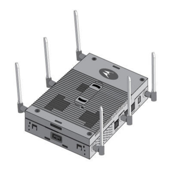
The AP-8132 is a plenum rated, 3x3:3 802.11n access point utilizing two 802.11abgn radios. An AP-8132 model access point uses WiNG 5 software as its onboard operating system. The access point’s unique WiNG 5 software enables the access point to function as either a Virtual Controller AP capable of adopting and managing up to 24 additional AP-8132 access points, a Standalone access point or a Dependent mode access point managed by its connected controller. -
Page 5: Warnings
• Verify cable lengths are within the maximum allowable distances for optimal signal transmission. 1.4 AP-8132 Package Contents An AP-8132 access point is available in external antenna models only. An AP-8132 ships with the following: • AP-8132 access point • AP-8132 Installation Guide (This Guide) •... - Page 6 • Features for snap-on module support through the access point’s USB interface • 3x3 MIMO, 3 spatial streams The AP-8132 access point has two RJ-45 connectors supporting 10/100/1000 Ethernet. GE1/POE accepts 802.3at or 802.3af compliant power from an external source...
-
Page 7: Hardware Installation
Hardware Installation 2.1 Installation Instructions An AP-8132 access point mounts either on a wall (with M4 x 25 pan head screws and wall anchor - or equivalent) or on a suspended ceiling T-bar. Once the AP-8132 is installed with facade and cabled, the cables (Ethernet and module connections) should not be visible when looking directly at the unit (ceiling and wall mounts). -
Page 8: Power Injector System
2.4 Power Injector System An AP-8132 model access point can receive power via an Ethernet cable connected to the GE1/POE (LAN) port. When users purchase a WLAN solution, they often need to place access points in obscure locations. In the past, a dedicated power source was required for each access point in addition to the Ethernet infrastructure. - Page 9 A separate Power Injector is required for each AP-8132 access point comprising the network. The Power Injector can be installed free standing, on an even horizontal surface or wall mounted using the power injector’s wall mounting key holes.
-
Page 10: Wall Mount Installation
A wall mount deployment requires hanging the AP-8132 access point along its width or length using two of three slots on the bottom of the unit. The AP-8132 can be mounted on to any plaster, wood or cement wall surface using the provided wall anchors. - Page 11 Installation Guide 2.5.1 Wall Mount Procedure - New Installation This section describes a new AP-8132 installation with no previous access point existing on the intended wall surface. 1. Place the access point against the wall, ensuring the access point’s Motorola Solutions “bat wings” logo is in the correct orientation.
-
Page 12: Suspended Ceiling T-Bar Mount Installation
2.6 Suspended Ceiling T-Bar Mount Instructions Ceiling mount requires holding the AP-8132 up against a T-bar of a suspended ceiling grid and twisting the unit on to the T-bar. If deploying the AP-8132 on a sculpted ceiling T-Bar, the access point mounting kit (Part No. - Page 13 Do not actually connect to the power source until the cabling portion of the installation is complete. 5. Verify the unit has power by observing the LEDs. For more information on AP-8132 LED behavior, see Indicators on page 19 6. Align the bottom of the ceiling T-bar with the back of the access point.
-
Page 14: Suspended Ceiling Tile (Plenum) Installation
Notes or warnings about suspended ceiling mounts apply to all NOTE installations where the unit is placed on suspended ceiling tile. Motorola does not recommend mounting the access point directly to CAUTION any suspended ceiling tile with a thickness less than 12.7mm (0.5in.) or a suspended ceiling tile with an unsupported span greater than 660mm (26in.). - Page 15 9. Fit the light pipe into hole in the tile from its unfinished side. 10. Slide the badge onto the light pipe from the finished side of the ceiling tile. 11. Attach the antennas to their correct connectors. For more information on supported AP-8132 antennas, AP-8132 Antenna Options on page 17...
- Page 16 Do not actually connect to the power source until the cabling portion of the installation is complete. 14. Verify the behavior of the access point LED light pipe. For more information on AP-8132 LED behavior, see LED Indicators on page 19 15.
-
Page 17: Ap-8132 Antenna Options
Installation Guide 2.8 AP-8132 Antenna Options Motorola Solutions supports two antenna suites for an AP-8132. One antenna suite supporting the 2.4 GHz band and another antenna suite supporting the 5 GHz band. Select an antenna model best suited to the intended operational environment of the AP-8132 access point. - Page 18 (Part No. ML-2452-PTA6M6-1) or serves as a plastic cover without an antenna (Part No. 21-8132FAC-01) For up-to-date information on supported antennas and antenna specifications, please refer to the Motorola Solutions Enterprise Wireless LAN Antenna Specification Guide available on the Motorola Solutions Web site.
-
Page 19: Led Indicators
Installation Guide 2.9 LED Indicators Both Integrated Antenna and External Antenna models have LED activity indicators on the front of the case. With the External Antenna models mounted above a ceiling, LEDs are at the center of an oval badge on the ceiling. The LEDs provide a status display indicating error conditions, transmission, and network activity for the 5 GHz 802.11an (amber) radio and the 2.4 GHz 802.11bgn (green) radio. - Page 20 AP-8132 Access Point Task 5 GHz Activity LED (Amber) 2.4 GHz Activity LED (Green) Firmware Update Locate AP LEDs blink in an alternating green, red and LEDs blink in an alternating green, red and Mode amber pattern using an irregular blink rate.
-
Page 21: Basic Access Point Configuration
Installation Guide Basic Access Point Configuration Once the AP-8132 is installed and powered on, complete the following steps to get the access point up and running and access management functions: 1. The access point’s IP address is optimally provided using DHCP. A zero config IP address can also be derived if DHCP resources are unavailable. - Page 22 AP-8132 Access Point 4. Enter the default password motorola in the Password field. 5. Click the Login button to load the management interface. When logging in for the first time, you’re prompted to change the NOTE password to enhance device security in subsequent logins.
- Page 23 Installation Guide The first page of the Initial Setup Wizard displays the Navigation Panel and Introduction for the configuration activities comprising the access point's initial setup A green checkmark to the left of an item in the Navigation Panel defines the listed task as having its minimum required configuration parameters set correctly.
- Page 24 AP-8132 Access Point The Introduction screen displays a list of the basic configuration activities supported by the Initial Setup Wizard. 7. Select Save/Commit within each page to save the updates made to that page's configuration. Select Next to proceed to the next page listed in the Navigation Panel. Select Back to revert to the previous screen in the Navigation Panel without saving your updates.
- Page 25 • Standalone AP -Select this option to deploy this access point as an autonomous fat access point. A Standalone AP isn't managed by a Virtual Controller AP, or adopted by a RFS series controller. If designating the access point as a Standalone AP, Motorola Solutions NOTE recommends the access point’s UI be used exclusively to define its device...
- Page 26 AP-8132 Access Point to define whether the access point receives an IP address using DHCP or if IP resources are provided statically. 10. Select Next. The Initial AP Setup Wizard displays the Access Point Mode screen to define the access...
- Page 27 Installation Guide 11. Select an Access Point Mode from the available options. • Router Mode - In Router Mode, the access point routes traffic between the local network (LAN) and the Internet or external network (WAN). Router mode is recommended in a deployment supported by just a single access point.
- Page 28 AP-8132 Access Point 12. Select Next. The Initial AP Setup Wizard displays the LAN Configuration screen to set the access point's LAN interface configuration. 13. Set the following DHCP and Static IP Address/Subnet information for the LAN interface: • Use DHCP - Select the checkbox to enable an automatic network address configuration using the access point’s DHCP server.
- Page 29 Installation Guide reserved for standard network services. This is a required parameter. • Default Gateway - Define a default gateway address for use with the default gateway. This is a required parameter. • DNS Forwarding - Select this option to allow a DNS server to translate domain names into IP addresses.
- Page 30 AP-8132 Access Point external network. This ports available differ depending on the access point model deployed. Access point models with a single port have this option fixed. • Enable NAT on the WAN Interface - Select the checkbox to allow traffic to pass between the access point's WAN and LAN interfaces.
- Page 31 Installation Guide Select Best to enable the access point to scan non-overlapping channels and listen for beacons from other access points. After the channels are scanned, it will select the channel with the fewest access points. In the case of multiple access points on the same channel, it will select the channel with the lowest average power level.
- Page 32 AP-8132 Access Point 19. Set the following parameters for each of the two WLAN configurations available as part of this Initial AP Setup Wizard: • SSID - Enter or modify the Services Set Identification (SSID) associated with the WLAN. The WLAN name is auto-generated using the SSID until changed by the user.
- Page 33 Installation Guide • RADIUS Server - If the WLAN type requires a RADIUS server to validate user credentials, designate whether the access point is using an External RADIUS Server resource or the access point's own Onboard RADIUS Server. If using an external RADIUS server resource, provide the IP address of the external server and the shared secret used to authenticate the request.
- Page 34 AP-8132 Access Point 21. Refer to the Username, Password, Description and Actions columns to review RADIUS Server user accounts. Add new accounts or edit the properties of existing accounts as updates are required. 22. Use the Add On-Board RADIUS Server Users field to set the following parameters for a user account: •...
- Page 35 • Location - Define the location of the access point. The Location parameter acts as a reminder of where the AP can be located within the Motorola Solutions managed wireless network. • Contact - Specify the contact information for the administrator. The credentials provided should accurately reflect the individual responding to service queries.
- Page 36 AP-8132 Access Point • Time Zone - Set the time zone where the access point is deployed. This is a required parameter. The setting should be complimentary with the selected deployment country. 26. If an NTP resource is unavailable, set the System Date and Time (calendar date, time and AM/PM designation).
- Page 37 Installation Guide 31. If the configuration displays as intended, select the Save/Commit button to implement these settings to the access point’s configuration. If additional changes are warranted based on the summary, either select the target page from the Navigational Panel, or use the Back and Next buttons to scroll to the target screen.
-
Page 38: Specifications
AP-8132 Access Point Specifications 4.1 Electrical Characteristics An AP-8132 model access point has the following electrical characteristics: Operating Current & 48VDC, 0.625A (AUX input voltage) Voltage 48VDC, 0.75A (PWRS-14000-247R power supply) 802.3at, 25.5W (AP-PSBIAS-2P3-ATR Power Injector) 4.2 Physical Characteristics An AP-8132 model access point has the following physical characteristics: Dimensions 9 inches x 6.00 inches x 1.75 inches... -
Page 39: Radio Specifications
Installation Guide 4.3 Radio Characteristics The AP-8132 model access point has the following radio characteristics: Data Rates Supported 802.11b: 1,2,5.5,11Mbps 802.11g: 1,2,5.5,11,6,9,12,18,24,36,48, and 54Mbps 802.11a: 6,9,12,18,24,36,48, and 54Mbps 802.11n: MCS 0-23 up to 450Mbps Wireless Medium Direct Sequence Spread Spectrum (DSSS),... -
Page 40: Regulatory Information
This device is approved under Motorola Solutions, Inc. This guide applies to the following Model Numbers: AP-8132. All Motorola/Symbol devices are designed to be compliant with rules and regulations in locations they are sold and will be labeled as required. -
Page 41: Health And Safety Recommendations
Installation Guide Industry Canada Statement: Caution: The device for the band 5150-5250 MHz is only for indoor usage to reduce potential for harmful interference to co-Channel mobile satellite systems. High power radars are allocated as primary users (meaning they have priority) of 5250-5350 MHz and 5650-5850 MHz and these radars could cause interference and/or damage to LE-LAN devices. -
Page 42: Us And Canada
This device must be powered from a 802.3af or 802.3at compliant power source which has been certified by the appropriate agencies, or by a LISTED Motorola, Type no. PWRS-14000-247R or AP-PSBIAS-2P3-ATR, direct plug-in power supply, marked Class 2 or LPS (IEC60950-1, SELV). -
Page 43: Radio Transmitters
Les types d'antenne non inclus dans cette liste, ou dont le gain est supérieur au gain maximal indiqué, sont strictement interdits pour l'exploitation de l'émetteur. Refer to section 2.8 of this guide for a listing of the 2.4 and 5 GHz antennas initially approved for use with the AP-8132. -
Page 44: Statement Of Compliance
Declarações Regulamentares para AP-8132 - Brasil Nota: A marca de certificação se aplica ao Transceptor, modelo AP-8132. Este equipamento opera em caráter secundário, isto é, não tem direito a proteção contra interferência prejudicial, mesmo de estações do mesmo tipo, e não pode causar interferência a sistemas operando em caráter primário. - Page 45 Installation Guide China Mexico Restrict Frequency Range to: 2.450 – 2.4835 GHz. S. Korea Taiwan 5.25-5.35 Thailand Turkish WEEE Statement of Compliance EEE Yönetmeliğine Uygundur...
- Page 46 : http://www.motorola.com/recycling/weee. Español: Para clientes en la Unión Europea: todos los productos deberán entregarse a Motorola al final de su ciclo de vida para que sean reciclados. Si desea más información sobre cómo devolver un producto, visite: http://www.motorola.com/recycling/weee.
- Page 47 Motorola-yhtiöön, kun tuotetta ei enää käytetä. Lisätietoja tuotteen palauttamisesta on osoitteessa http://www.motorola.com/recycling/weee. Dansk: Til kunder i EU: Alle produkter skal returneres til Motorola til recirkulering, når de er udtjent. Læs oplysningerne om returnering af produkter på: http://www.motorola.com/recycling/weee. Ελληνικά: Για πελάτες στην Ε.Ε.: Όλα τα προϊόντα, στο τέλος της διάρκειας...
-
Page 48: Part Numbers, Support, And Sales
• Model number or product name • Software type and version number Motorola Solutions responds to calls by email or telephone within the time limits set forth in support agreements. If you purchased your Enterprise Mobility business product from a Motorola Solutions business partner, contact that business partner for support. -
Page 49: Motorola Solutions, Inc. End-User License Agreement
BIND THAT COMPANY, PERSON OR ENTITY. LICENSE GRANT. Subject to the terms of this Agreement, Motorola, Inc. and/or its subsidiaries ("Licensor") hereby grants Licensee a limited, personal, non-sublicensable, non-transferable, nonexclusive license to use the software that Licensee is about to download or install and the documentation that accompanies it (collectively, the "Software") for Licensee's personal use in connection with... - Page 50 FAR, 48 CFR 52.227-14 (JUNE 1987) or DFAR, 48 CFR 252.227-7013 (OCT 1988), as applicable. The "Manufacturer" for purposes of these regulations is Motorola, Inc., One Symbol Plaza, Holtsville, NY 11742. EXPORT RESTRICTIONS. Licensee shall comply with all export laws and restrictions and regulations of the Department of Commerce, the United States Department of Treasury Office of Foreign Assets Control ("OFAC"), or other United States or foreign agency or...
- Page 51 Installation Guide MISCELLANEOUS. Licensee may not sublicense, assign, or transfer this Agreement, or its rights or obligations hereunder, without the prior written consent of Licensor. Any attempt to otherwise sublicense, assign, or transfer any of the rights, duties, or obligations hereunder is null and void.
-
Page 52: Ap-8132 Access Point China Rohs Compliance
塑料和聚合物部件 (Plastic and Polymeric Parts) 光学和光学组件 (Optics and Optical Components) 电池 (Batteries) O: 表示该有毒有害物质在该部件所有均质材料中的含量均在 SJ/T11363-2006 标准规定的限量要求以 下。 X: 表示该有毒有害物质至少在该部件的某一均质材料中的含量超出 SJ/T11363-2006 标准规定的限量 要求。 对销售之日的所售产品,本表表示,公司供应链的电子信息产品可能包含这些物质。注意:在所售产品 中可能会也可能不会含有所有所列的部件。 This table was created to comply with China RoHS requirements for Motorola Solutions‘ AP-8132 Access Point. - Page 53 Installation Guide...
- Page 54 Schaumburg, IL 60196-1078, U.S.A. http://www.motorolasolutions.com MOTOROLA, MOTO, MOTOROLA SOLUTIONS and the Stylized M Logo are trademarks or registered trademarks of Motorola Trademark Holdings, LLC and are used under license. All other trademarks are the property of their respective owners. © 2012 Motorola Solutions, Inc. All Rights Reserved.
Need help?
Do you have a question about the AP-8132 and is the answer not in the manual?
Questions and answers