Heatrae Sadia ELECTROMAX Installation & Servicing Instructions Manual
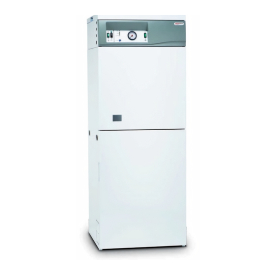
Combined electric flow boiler
and direct unvented water heater
Hide thumbs
Also See for ELECTROMAX:
- Installation & servicing instructions manual (44 pages) ,
- User instructions (13 pages) ,
- Installation & servicing instructions manual (44 pages)
Table of Contents
Advertisement
Quick Links
Advertisement
Table of Contents

Related Manuals for Heatrae Sadia ELECTROMAX


Summary of Contents for Heatrae Sadia ELECTROMAX
- Page 1 ELECTROMAX INSTALLATION & Combined Electric Flow Boiler and Direct Unvented Water Heater SERVICING INSTRUCTIONS Please read and understand these instructions before starting work Please leave this leaflet with the user following installation and commissioning Installation & Servicing Instructions...
-
Page 2: Table Of Contents
1.4 Contents Check List Safety Valves 2.0 Technical Data 7.4 Set the Programmable Room 3.0 General Requirements Thermostat 3.1 Location of the Electromax 7.5 Preliminary Electrical Checks 3.2 Water Supply 7.6 Check Operation of the 3.3 Pipework, Fittings and Outlet/ Electric Boiler Terminal Fittings 7.7 Setting the Automatic By-pass... -
Page 3: Introduction
1.1 Important Notes is done by means of an Off-Peak electrical supply. The Electromax must be installed in accordance with the manufacturer’s instructions and all The use of an Off-Peak tariff that provides at relevant regulations in force at the time of least three off peak electricity periods, such installation. -
Page 4: Storage, Unpacking And Handling
Programmable Room Within the Electromax packaging the following Thermostat which is supplied loose with the components are supplied. Please check that Electromax for remote siting in a suitable, all parts are available before commencing convenient position. installation. -
Page 5: Technical Data
Global warming potential 3.1 Com ple te unit ) l l Packaged dimensions H x W x D (mm) Electromax unit : 1566 x 600 x 650 Installation kit : 320 x 315 x 610 Cylinder Performance Off Peak heater 3kW... - Page 6 Minimum clearance Lifting Points over Top Panel for In Upper Rear access Panel LEFT HAND FRONT SIDE Tundish Viewing Window Side Panel Lifting Points (Mirrored in Right Hand Side Panel) Min. clearance either side Lifting Points In Base Diagram 1 Dimensions Installation &...
- Page 7 Primary System Primary System Expansion Vessel Expansion Vessel Air Valve Primary Circulating Primary System Pump Expansion Vessel Connection Electric Control Circuitry Automatic Air Vent (Mounted Behind Fascia) Top Panel Fascia Panel User Interface Panel Electrical Connection Panel Mounted Fuses 3 amp Terminal Blocks Primary System Pressure Boiler Electronic Control...
- Page 8 SPEED SPEED INPUT FULL LOAD LOCKED ROTOR SETTING R.P.M. POWER (W) CURRENT (A) CURRENT (A) 2300 0.23 0.30 2100 0.20 0.25 1700 0.16 0.20 H (m) 0.2 0.4 0.6 0.8 1.0 1.2 1.4 1.6 1.8 2.0 2.2 2.4 2.6 2.8 3.0 Q (m /h) Diagram 3 Pump Characteristics Diagram 4 Automatic Bypass Valve Characteristics 1200...
-
Page 9: General Requirements
3.1 Location of the Electromax available pressure and flowrate the better the system performance will be. The Electromax must not be sited outside or in any location where it could be exposed to The Electromax unvented cylinder has an the weather. It must be installed in a dry and operating pressure of 3.5 bar which is controlled... -
Page 10: Pipework, Fittings And Outlet/Terminal Fittings
The Electromax unvented cylinder can be used pump and valves, system noise and circulation in conjunction with most types of terminal problems. -
Page 11: Sealed Primary Systems
3.5 Sealed Primary Systems likely to collect. The Electromax boiler must be installed in a An automatic bypass valve is fitted to the sealed primary system. All necessary primary Electromax to allow thermostatic radiator system controls are supplied fitted to the valves to be fitted to the system. -
Page 12: Installation - General
4.1 Positioning the Electromax recesses either side of the panel. Once removed, the two M5 screws securing the Decide where the Electromax is to be installed. lower edge of the upper front panel must be Reference must be made to the dimensions removed. -
Page 13: Cable Entry Positions
4.3 Cable Entry Positions 4.4 Programmable Room Thermostat The electrical supply cables can be routed to The Electromax is supplied with a Danfoss enter the unit from the left or right hand side TP5000 Programmable Room Thermostat. This (see diagram 8, page 13). There are four cable is in the accessory kit supplied with your unit. -
Page 14: Installation - Plumbing
Whilst to the cold water supply to the Electromax to it is often more convenient to do so, there is accommodate any water expansion that results no requirement to site the valve close to the from heating the water inside the cylinder. -
Page 15: Balanced Cold Water Supplies
5.6 Secondary Circulation handle temperatures of 99°C or greater should be used. Secondary circulation is not recommended for the Electromax as it is intended for Off- The following extract is taken from the latest Peak electrical operation. - Page 16 3.53 Where valves other than the product and performance standard (e.g. temperature and pressure relief valve from a as specified in the relevant part of BS 7291). single unvented hot water system discharge by way of the same manifold that is used by the 3.58 The discharge pipe (D2) should be safety devices, the manifold should be factory...
- Page 17 polyethylene (PE-X) to Class S of BS 7291- Worked example of discharge pipe sizing 3:2006; and (d) be continuously marked with a warning Diagram 11, page 18: shows a G1/2 temperature that no sanitary appliances should be relief valve with a discharge pipe (D2) having 4 connected to the pipe.
- Page 18 MINIMUM MINIMUM SIZE MAXIMUM RESISTANCE RESISTANCE VALVE SIZE OF OF DISCHARGE ALLOWED, EXPRESSED CREATED BY OUTLET SIZE DISCHARGE PIPR D2 FROM AS A LENGTH OF EACH ELBOW OR PIPE D1 TUNDISH STRAIGHT PIPE BEND 22mm UP TO 9M 0.8M G 1/2 15mm 28mm UP TO 18M...
-
Page 19: Primary (Central Heating) Pipework
Electromax boiler to be isolated from the primary circuit for maintenance and A filling loop is provided within the Electromax servicing. -
Page 20: Installation - Electrical
Other Off-Peak tariffs may be suitable, consult property must be of sufficient current rating the Heatrae Sadia Specification Team or your and voltage for the Electromax and any other electricity supplier for further advice. electrical requirements for the property. With an Off-Peak electrical supply there will be... - Page 21 24 Hour supply connection (NB NOT Boiler connection) A suitable electrical connection must be taken from the 24 Hour supply to the Electromax terminal block. The supply cable should be 1.5mm cross sectional area 3 core HOFR sheathed cable and must be routed into the Electromax via one of the 20mm cable glands previously fitted (see section 3.3, page 10).
-
Page 22: Boiler Connection
The supply cable 14 (schematic wiring diagram). Connection to should be a minimum of 10mm cross sectional the Electromax should be with 2 core cable area, (check the IEE Wiring Regulations for of 0.5mm to 1.0mm cross sectional area correct cable sizing). -
Page 23: Commissioning
(see diagram 15, page 23). (d) Open the cold water supply isolating valve and allow the Electromax cylinder to fill. When water issues from the tap, allow to run for a few minutes to thoroughly flush... -
Page 24: Filling The Sealed System Primary Circuit
Valve 1.0 bar. If it has re-connect the filling loop on the Electromax (see diagram 16, page and refill until the gauge reads between 24). Check water discharged runs freely 1.0 and 1.5 bar. -
Page 25: Set The Programmable Room Thermostat
7.4 Set The Programmable Room (1 to 5 on the thermostat). If required Thermostat the thermostats should be readjusted by isolating the electrical supply to the (a) Fit batteries supplied immersion heaters and then removing the programmable room thermostat. The immersion heater covers and rotating the battery compartment is located behind thermostat adjustment knob (see diagram... -
Page 26: Setting The Automatic By-Pass Valve
Diagram 19 Fascia Panel Features - Radiator Model Graphics Shown modulates the power. 7.7 Setting the Automatic By-pass Valve (g) Check the primary FLOW pipework from the Electromax begins to rise in (a) Loosen the brass locking screw on top of temperature. the adjustment cap of the by-pass valve (h) When the boiler is operating at its (see diagram 42, page 39). -
Page 27: Check Operation Of The Immersion Heaters
7.8 Check Operation of the Immersion 7.9 Demonstration to User Heaters Following commissioning any panels or covers (a) The Off-Peak immersion heater removed must be replaced and fully secured controlled by the Off-Peak electrical in place. The system, its function and control supply and will only switch on during Off- should be fully explained to the user. -
Page 28: Maintenance
In hard water areas where no water treatment performance of the Electromax it should be measures have been taken the immersion regularly maintained. Maintenance should be heaters may require descaling. The Electromax carried out by a competent person and any... -
Page 29: Operation Of Cylinder Safety Valves
8.5 Operation of Primary System Safety heater and gently lever up and down. (g) Carefully remove any scale from the surface Valve of the immersion heater elements. DO (a) Close the primary flow and return isolating NOT use a sharp implement as damage valves (see diagram 15, page 23). -
Page 30: Electrical Checks
and when correct replace the dust cap. (e) Connect the filling loop. Open the filling loop isolating valves and allow system to re-pressurise to approx. 1.5 bar. (f) Close the filling loop isolating valves and remove the flexible hose. (g) Open the primary flow and return isolating valves. -
Page 31: Fault Finding And Servicing
SUPPLY FAULT HOUR & 45 AMP SUPPLIES FINDING TERMINALS diagnose problems with the Electromax unit. These checks should be carried out by a competent installer or an authorized Heatrae Sadia service engineer or agent. A range of DOES THE CH ON SWITCH replacement parts (see section 9.2, page 35) - Page 32 THERE IS NO WATER IN THE SYSTEM. IS THERE ALARM TRIPS DURING SWITCH OFF 240V AT THE SELF CHECKING BUT IMMEDIATELY. DEMAND INDICATOR ROOM THERMOSTAT NOT INSTANTLY CHECK 3 AMP PANEL CHECK AND REFILL FAULTS CONNECTIONS MOUNT FUSE BEFORE RESTARTING CHECK PROG.
- Page 33 OPERATED GO TO T&P RELIEF VALVE FAULT FINDING REPLACE THERMOSTAT SWITCH OFF WATER HEATER. CONTACT HEATRAE SADIA Diagram 31 Water Heater Fault Finding Off Peak Diagram 30 Water Heater Fault Finding Master (Lower) Immersion Heater Faults Installation & Servicing Instructions...
- Page 34 IS 240V CHECK 24 HOUR BOOST (UPPER) SUPPLY AT CHECK INTERNAL ELECTRICAL SUPPLY IMM. HEATER NOT 24 HOUR WIRING IS ON OPERATING TERMINALS IS 240V IS 240V SUPPLY AT SUPPLY AT PRESS BOOST BOOST (UPPER) BOOST (UPPER) SWITCH THERMOSTAT THERMOSTAT TERMINALS TERMINALS NOTE:...
-
Page 35: Replacement Parts
Heatrae A range of replacement parts is available for Sadia service engineers or agents. the Electromax unit. Refer to the following diagrams to aid in identifying the parts you require and the relevant Heatrae Sadia order code. - Page 36 Spares list Pump Assembly Replacement Parts Description Part Number Auto air vent and extension 95605031 Pump 95605032 Diagram 37 - Pump Assembly Element Assembly Replacement Parts Description Part Number Immersion heater (upper) 95606963 Immersion heater (lower) 95606964 Immersion heater gasket 95611822 Immersion heater backnut 95607869...
-
Page 37: Servicing
ANY WORK ON THE UNIT. THE WATER unit. CONTAINED IN EITHER THE WATER HEATER (b) Open a hot tap supplied by the Electromax CYLINDER OR THE PRIMARY HEATING to relieve the system pressure. Caution: CIRCUIT MAY BE VERY HOT – CARE MUST some hot water will flow from the tap! BE TAKEN TO AVOID SCALDING. - Page 38 (f) Replacement is a reversal of the above procedure. Ensure the pump sealing Pump Extension Auto Air washers are correctly located before Vent tightening union nuts. Ensure the correct Pump electrical connections are made (Brown O Ring wire to “L” terminal, Blue wire to “N” terminal, Green/Yellow wire to “...
- Page 39 9.3.6 Removing the Automatic Bypass Valve (see diagram 42, page 39) Automatic Bypass (a) Drain primary circuit. Valve (b) Unscrew the compression connections at inlet and outlet of the valve. (c) Remove the automatic bypass valve. Primary Off Peak (d) Replacement is a reversal of the above Flow Immer- procedure.
- Page 40 9.3.8 Removing Primary System Expansion Vessel (see diagram 44, page Primary Expansion Vessel (a) Drain primary circuit. (b) Unscrew union nut at connection between Support the expansion vessel and the flexible hose Nest coupling. (c) Lift expansion vessel from moulded support nest.
- Page 41 9.3.10 Removing the Electric Boiler Main Control PCB Terminal Blocks (a) Remove cover from over the electric boiler control pcb (see diagram 43, page 39). (b) Disconnect cables from the terminal blocks. (c) Unplug ribbon cable connector CONN 2. (d) Unplug the thermistor connector from CONN 5 CONN 4.
- Page 42 9.3.12 Removing the Front Fascia Panel (see diagram 48, page 42) Front facia panel (a) Drain primary circuit. (b) Unscrew the securing screws from the top of the front fascia moulding (note: these screws can only be accessed with the top panel removed).
-
Page 43: Guarantee
• Any valves and controls fitted are of and a Global Warming Potential (GWP) of 3.1. Heatrae Sadia recommended type and specification. • The unit has not been modified or tampered with in any way and has been regularly maintained as detailed in these instructions. -
Page 44: Spares Stockists
Bristol BS32 4TF Tel: 01454 620500 The policy of Heatrae Sadia Heating is one of continuous product development and, as such, we reserve the right to change specifications without notice. Service Tel: 0844 871 1535 Service Fax: 0844 871 1528 Service Email: heatraesadiaservice@ heateam.co.uk...
Need help?
Do you have a question about the ELECTROMAX and is the answer not in the manual?
Questions and answers