Heatrae Sadia ELECTROMAX Installation & Servicing Instructions Manual
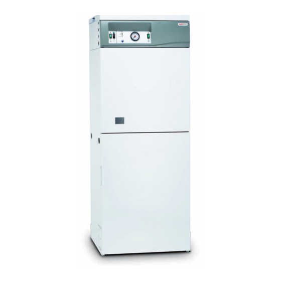
Combined electric flow boiler and direct unvented water heater
Hide thumbs
Also See for ELECTROMAX:
- Installation & servicing instructions manual (44 pages) ,
- User instructions (13 pages) ,
- Installation & servicing instructions manual (44 pages)
Table of Contents
Advertisement
Advertisement
Table of Contents

Related Manuals for Heatrae Sadia ELECTROMAX


Summary of Contents for Heatrae Sadia ELECTROMAX
- Page 1 ELECTROMAX INSTALLATION & Combined Electric Flow Boiler and Direct Unvented Water Heater SERVICING INSTRUCTIONS Please read and understand these instructions before starting work Please leave this leaflet with the user following installation and commissioning Installation & Servicing Instructions...
-
Page 2: Table Of Contents
1.4 Contents Check List Safety Valves 2.0 Technical Data 7.4 Set the Programmable Room 3.0 General Requirements Thermostat 3.1 Location of the Electromax 7.5 Preliminary Electrical Checks 24 3.2 Water Supply 7.6 Check Operation of the 3.3 Pipework, Fittings and Outlet/ Electric Boiler Terminal Fittings 7.7 Setting the Automatic By-pass... -
Page 3: Introduction
1.2 Basic operation of the Electromax operation of the Electromax, the central heating system and associated controls The Electromax is an integrated electric flow should be explained to the customer and boiler and direct electrically heated unvented these instructions left with them for future domestic water heating cylinder. -
Page 4: Storage, Unpacking And Handling
Time and temperature control of the central guidelines. heating is by means of a Programmable Room Thermostat which is supplied loose with the Electromax for remote siting in a 1.4 Contents check list suitable, convenient position. Within the Electromax packaging the following The necessary cold water mains supply components are supplied. -
Page 5: Technical Data
Global W arming potential 3.1 Com ple te unit ) l l Packaged dimensions H x W x D (mm) Electromax unit : 1566 x 600 x 650 Installation Kit : 320 x 315 x 610 Cylinder Performance Off Peak heater 3kW... - Page 6 Diagram 1 Dimensions Minimum clearance Lifting Points over Top Panel for In Upper Rear access Panel LEFT HAND FRONT SIDE Tundish Viewing Window Side Panel Lifting Points (Mirrored in Right Hand Side Panel) Min. clearance either side Lifting Points In Base Installation &...
- Page 7 Diagram 2 Key Components Primary System Primary System Expansion Vessel Expansion Vessel Air Valve Primary Circulating Primary System Pump Expansion Vessel Connection Electric Control Circuitry Automatic Air Vent (Mounted Behind Fascia) Top Panel Fascia Panel User Interface Panel Electrical Connection Panel Mounted Fuses 3 amp Terminal Blocks Primary System Pressure...
- Page 8 Diagram 3 Pump Characteristics SPEED SPEED INPUT FULL LOAD LOCKED ROTOR SETTING R.P.M. POWER (W) CURRENT (A) CURRENT (A) 2300 0.23 0.30 2100 0.20 0.25 1700 0.16 0.20 H (m) 0.2 0.4 0.6 0.8 1.0 1.2 1.4 1.6 1.8 2.0 2.2 2.4 2.6 2.8 3.0 Q (m /h) Diagram 4 Automatic Bypass Valve Characteristics 1200 1500...
-
Page 9: General Requirements
3.1 Location of the Electromax Wherever possible the mains water supply pipe should be in 22mm OD (copper) or The Electromax must not be sited outside or 25mm OD (Blue MDPE). The minimum mains in any location where it could be exposed to water supply requirements should be 1.0 bar... -
Page 10: Pipework, Fittings And Outlet/Terminal Fittings
Electromax immediately after the Cold Water Combination Valve (see diagram 5). Electromax Housing Unvented Cylinder Unvented System... -
Page 11: Sealed Primary Systems
3.5 Sealed Primary Systems likely to collect. The Electromax boiler must be installed in a An automatic bypass valve is fitted to the sealed primary system. All necessary primary Electromax to allow thermostatic radiator system controls are supplied fitted to the valves to be fitted to the system. -
Page 12: Installation - General
4.1 Positioning the Electromax The lower front panel (Panel A on Diagram 7) is secured by spring clips and is removed Decide where the Electromax is to be by pulling forward using the finger recesses installed. Reference must be made to the either side of the panel. -
Page 13: Cable Entry Positions
4.3 Cable Entry Positions 4.4 Programmable Room Thermostat The electrical supply cables can be routed to The Electromax is supplied with a Danfoss enter the unit from the left or right hand side TP5000 Programmable Room Thermostat. (see Diagram 8). There are four cable entry This is supplied in the accessory kit supplied holes in each upper side panel;... -
Page 14: Installation - Plumbing
Electromax a point remote from the unit if this is more to accommodate any water expansion that convenient. -
Page 15: Balanced Hot Water Supplies
Secondary circulation is not recommended systems it is essential that the tundish is fitted in a visible position as the final point for the Electromax as it is intended for Off-Peak electrical operation. During other of discharge will not be visible. Consult periods the electricity supply is interrupted the manufacturer’s recommendations with... - Page 16 Water may drip from the discharge pipe of b. have a vertical section of pipe at least the pressure-relief device and that this pipe 300mm long below the tundish before any must be left open to the atmosphere. elbows or bends in the pipework. The pressure-relief device is to be operated c.
- Page 17 Worked example of discharge pipe Subtract the resistance allowed for 4 No. sizing 22mm elbows at 0.8m each = 3.2m The example below is for a G1/2 temperature Therefore the permitted length equates to: relief valve with a discharge pipe (D2) having 5.8m 4 No.
-
Page 18: Primary (Central Heating) Pipework
A filling loop is provided within the unit on the primary flow and return connections Electromax casing to fill the primary to enable the Electromax boiler to be isolated circuit directly from the cold water supply. from the primary circuit for maintenance and When the system is full and correctly servicing. -
Page 19: Installation - Electrical
Electromax unit it property must be of sufficient current rating should be connected to an Off-Peak electrical and voltage for the Electromax and any other supply. The “Economy 10” tariff, which is electrical requirements for the property. - Page 20 24 Hour supply connection (NB NOT Boiler connection) A suitable electrical connection must be taken from the Off Peak supply to the Electromax A suitable electrical connection must be taken terminal block. The supply cable should from the 24 Hour supply to the Electromax be 1.5mm...
-
Page 21: Boiler Connection (45 Amp)
240V supply, Regulations for correct cable sizing). It must bell wire MUST NOT be used. The cable be routed into the Electromax via the 25mm must be routed into the Electromax via one cable gland previously fitted (see section of the 20mm cable glands previously fitted 3.3, page 10). -
Page 22: Commissioning
Check all connections (including CORRECTLY FILLED WITH WATER immersion heater connections) for leaks and rectify as necessary. 7.1 Filling The Electromax Cylinder g. The strainer housed within the Cold Water Combination Valve should be a. Check that all connections to the cleaned to remove any debris that Electromax are tight. -
Page 23: Filling The Sealed System Primary Circuit
7.3 Check The Operation of the Safety c. Repeat the above steps for the Valves Primary System Pressure Relief Valve on the Electromax (see Diagram 16). a. Slowly manually open, for a few After this operation check that the seconds, the Temperature and Pressure... -
Page 24: Set The Programmable Room Thermostat
7.4 Set The Programmable Room c. The electrical system should be Thermostat checked for Earth Continuity, Short Circuits, Polarity and Resistance to a. Fit the batteries supplied to the Earth. Programmable Room Thermostat. d. The immersion heaters are factory set The battery compartment is located to give a hot water storage temperature behind the hinged cover under a snap... -
Page 25: Setting The Automatic By-Pass Valve
Check the primary FLOW pipework valve. from the Electromax begins to rise in c. With the boiler on (“DEMAND” and temperature. “HEAT” indicators illuminated) and h. When the boiler is operating at its the pump running, slowly turn the maximum power output (“HEAT”... -
Page 26: Check Operation Of The Immersion Heaters
(indicated by a “tap” symbol, e. User Instructions – see Diagram 19, page 25). The switch Hand over the Electromax Installation should be illuminated when on. Instructions, the Danfoss TP 5000 d. Press the DHW Boost switch (indicated Installation and User Instructions and by a “tap”... -
Page 27: Maintenance
To e n s u r e t h e c o n t i n u e d o p t i m u m be 3.5 bar. If lower than the required performance of the Electromax it should be setting it should be re-charged using regularly maintained. -
Page 28: Operation Of Cylinder Safety Valves
e. Disconnect the wiring from the m. When water flows from the hot tap immersion heater thermostats. allow to flow for a short while to purge Remove the thermostats by carefully air and flush through any disturbed pulling outwards from the immersion particles. -
Page 29: Electrical Checks
d. Check the charge pressure of the Vessel using a tyre pressure gauge. The pressure (with system de-pressurised) should be 1.0 to 1.2 bar. If lower than the required setting it should be re- charged using a tyre pump (Schrader valve type). -
Page 30: Fault Finding And Servicing
These checks should be carried out FINDING TERMINALS by a competent installer or an authorized Heatrae Sadia service engineer or agent. A range of replacement parts (see Section 9.2) DOES THE is available should any major component CH ON SWITCH... - Page 31 Diagram 25 Electric Boiler Fault Finding Diagram 28 Electric Boiler Fault Finding Alarm 2 Demand Faults 1 THERE IS NO WATER IS THERE IN THE SYSTEM. 240V AT THE ALARM TRIPS DURING SWITCH OFF DEMAND INDICATOR ROOM THERMOSTAT SELF CHECKING BUT CHECK 3 AMP PANEL IMMEDIATELY.
- Page 32 TO POSITION 4 TO 5 TEMPERATURE GO TO EXPANSION RELIEF VALVE FAULT FINDING THE THERMAL RE-SET THERMAL CUT-OUT CUT-OUT OPERATED GO TO T&P RELIEF VALVE FAULT FINDING REPLACE THERMOSTAT SWITCH OFF WATER HEATER. CONTACT HEATRAE SADIA Installation & Servicing Instructions...
- Page 33 Diagram 32 Water Heater Fault Finding Boost (upper) Immersion Heater Faults IS 240V CHECK 24 HOUR BOOST (UPPER) SUPPLY AT CHECK INTERNAL ELECTRICAL SUPPLY IMM. HEATER NOT 24 HOUR WIRING IS ON OPERATING TERMINALS IS 240V IS 240V SUPPLY AT SUPPLY AT PRESS BOOST BOOST (UPPER)
- Page 34 Diagram 34 Water Heater Fault Finding Expansion Valve Faults CHECK DHW DISCHARGE EXPANSION RELIEF EXPANSION INTERMITTENT VALVE DISCHARGES VESSEL CHARGE PRESSURE IS 3.5 BAR CHECK COLD WATER DISCHARGE COMBI VALVE CONTINUOUS PRESSURE REDUCER CONTROLS AT 3.5 BAR. CHECK EXPANSION VALVE OPERATION. Diagram 35 Water Heater Fault Finding Temperature &...
-
Page 35: Replacement Parts
A range of replacement parts is available for authorized Heatrae Sadia service engineers the Electromax unit. Refer to the following or agents. diagrams to aid in identifying the parts you require and the relevant Heatrae Sadia order code. - Page 36 Diagram 37 - Pump Assembly Pump Assembly Replacement Parts i r c 1. Auto air vent and extension 95605031 Diagram 38 - Element Assemblies Element Assembly Replacement Parts i r c 1. Immersion heater (upper) 95606963 2. Immersion heater (lower) 95606964 3.
-
Page 37: Servicing
(see Diagram 20, page 27). Place the discharge point of the hose at a point 9.3.1 Draining the Electromax Primary below the level of the Electromax Circuit where the water drained will safely a. To avoid draining the complete primary drain away. - Page 38 9.3.4 Removing the Primary circulating Diagram 40 Pump Removal pump (see Diagram 40) Pump Extension Auto Air a. Drain primary circuit. Vent b. Unscrew top of Pump electrical housing Pump O Ring and remove by pulling upwards. c. Unscrew Pump cable securing gland. Disconnect Pump connections from O Ring terminals by pressing the spring...
- Page 39 9.3.6 Removing the Automatic Bypass Diagram 42 Auto By-pass Valve Removal Valve (see Diagram 42) Automatic a. Drain primary circuit. Bypass b. Unscrew the compression connections Valve at inlet and outlet of the Valve. c. Remove the Automatic Bypass Valve. Primary Off Peak Flow...
- Page 40 9.3.8 Removing the Primary System Diagram 44 Primary Expansion Vessel Expansion Vessel (see Diagram 44) Removal a. Drain primary circuit. Primary Expansion b. Unscrew union nut at connection Vessel between the Expansion Vessel and the flexible hose coupling. Support c. Lift Expansion Vessel from moulded Nest support nest.
- Page 41 9.3.10 Removing the Electric Boiler Main Diagram 46 Electric Boiler Control PCB Control PCB Terminal Blocks a. Remove cover from over the Electric Boiler Control pcb (see Diagram 43, page 39). b. Disconnect cables from the terminal blocks. c. Unplug ribbon cable connector CONN d.
- Page 42 9.3.12 Removing the Front Fascia Panel Diagram 48 Fascia Panel Removal (see Diagram 48) Front Fascia a. Drain primary circuit Panel b. Unscrew the securing screws from the top of the front fascia moulding (Note: these screws can only be accessed with the Top Panel removed).
-
Page 43: Guarantee
Global Warming Potential (GWP) of and safety valves have been fitted correctly. 3.1. • Any valves and controls fitted are of Heatrae Sadia recommended type and specification. • The unit has not been modified or tampered with in any way, and has been regularly maintained as detailed in these instructions. -
Page 44: Spares Stockists
Unit 3A, 780 South Street, Whiteinch, Glasgow, G14 0SY Tel: 0141 434 1530 The policy of Heatrae Sadia Heating is one of continuous product development and, as such, we reserve the right to change specifications without notice. Service Tel: 0844 871 1535...
Need help?
Do you have a question about the ELECTROMAX and is the answer not in the manual?
Questions and answers
How often should the boiler be serviced? Heatrae sadia electro max