Heatrae Sadia Multipoint ECO 100L V 3kW Installation, Operation And Maintenance Manual
Hide thumbs
Also See for Multipoint ECO 100L V 3kW:
Table of Contents
Advertisement
Quick Links
Advertisement
Table of Contents

Related Manuals for Heatrae Sadia Multipoint ECO 100L V 3kW


Summary of Contents for Heatrae Sadia Multipoint ECO 100L V 3kW
- Page 1 Multipoint ECO Vertical 30 - 100 Litres Installation, operation and maintenance manual WARNING This water heater must only be installed by qualified persons. Please read and understand these instructions before starting work. Please leave this leaflet with the user following installation.
-
Page 2: Table Of Contents
Contents 11. Warranty ..............30 11.1 General ..............30 11.2 Warranty conditions ..........30 1. Introduction ...............3 11.3 Water supply requirements ........30 1.1 General ..............3 11.4 Claims under warranty ..........30 1.2 Symbols used ............3 11.5 Exclusions ............30 1.3 Abbreviations ............3 12. Decommissioning ...........31 1.4 Liabilities ..............3 12.1 Decommissioning procedure ........31 2. -
Page 3: Introduction
1. Introduction Failure to abide by the instructions for using the appliance. 1.1 General Faulty insufficient maintenance appliance. The following instructions are offered as a guide to the Failure to abide by the instructions for installing the user and Installer. The installation must be carried out by a product. -
Page 4: Safety
How hot water can be drained. (see page 25 for CAUTION more details) Annual maintenance is recommended and The type or characteristics of the Pressure should to be carried out by a competent person, see section 9, page 24. Reducing device and how to connect it; (see Figure 9, page 24 for exploded view) A discharge pipe connected to the temperature/ 2.3 Specific safety instructions... -
Page 5: Technical Specifications
3. Technical specifications 3.1 Technical data Multipoint ECO Multipoint ECO Multipoint ECO Multipoint ECO Product Name 30L V 3kW 50L V 3kW 80L V 3kW 100L V 3kW Product Code 7693979 7693981 7693983 7694025 Electrical rating 3.0kW @ 240V ~ / 2.8kW @ 230V Max Inlet Pressure to PRV 1.6 MPa (16.0 bar) Weight Empty kg... -
Page 6: Dimensions And Connections
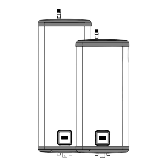
3.2 Dimensions and connections Figure 1: General dimensions Item 30L V 3kW 50L V 3kW 80L V 3kW 100L V 3kW Same as A2 Same as A2 1028 1084 1253 1134 OUTLET 22mm / 3/4"BSP (M) INLET 22mm / 3/4"BSP (M) TEMPERATURE / PRESSURE RELIEF VALVE. -
Page 7: Electrical Diagram(S)
3.3 Electrical diagram(s) Outer Case Power On Indicator (Neon) HE1 W6 Not Used HE2 W4 Heating Element HE1 W3 HE2 W5 Electronic Control (IBD 12003 Controller) Thermostat CON1 Ribbon Cable (ICB00005) SMART Controller (IFG90007) Figure 2: Wiring Diagram... -
Page 8: Description Of The Product
4. Description of the product 4.1 General description This appliance is a purpose designed unvented water heater. The water heater has a stainless steel inner vessel, which ensures an excellent standard of corrosion resistance. The outer casing is a combination of resilient thermoplastic mouldings and coated corrosion proofed steel sheet. -
Page 9: Before Installation
Situations where maintenance is likely to be 5. Before installation neglected or safety devices tampered with. Water supplies that have either inadequate 5.1 Installation regulations pressure or where the supply may be intermittent. Situations where it is not possible to safely pipe away any discharge from the safety valves. -
Page 10: Installation
6. Installation CAUTION If this appliance is installed into a location where the temperature of the air surrounding (ambient) the water heater constantly exceeds C, then additional ventilation should be considered. 6.1 General After reading the previous sections in this booklet and choosing a suitable location for the appliance please install, paying attention to the following water, electrical and commissioning sections. - Page 11 A suitable drain off valve should be installed in the cold water supply to the appliance between the Expansion Valve and the appliance at as low a level as possible. It is recommended that the outlet point of the drain pipework be at least 1 metre below the level of the base of the appliance (this can be achieved by attaching a hose to the drain off valve spigot).
- Page 12 the valve, with no more than 600mm of pipe between Discharge the valve outlet and the tundish (see Fig 7). It is a requirement of Building Regulation G3 that any Note: To comply with the Water Supply (Water Fittings) discharge from an unvented system is conveyed to Regulations, the tundish should incorporate a suitable where it is visible, but will not cause danger to persons in air gap.
- Page 13 Worked example of discharge pipe sizing through the tundish; (b) be a separate branch pipe with no sanitary appliances connected to it; Fig. 7: shows a G1/2 temperature relief valve with a (c) if plastic pipes are used as branch pipes carrying discharge pipe (D2) having 4 No.
- Page 14 Maximum Resistance Minimum Size Of Minimum Size Of Resistance Valve Allowed, Expressed As A Discharge Pipe Discharge Pipe D2 Created By Each Outlet Size Length Of Straight Pipe From Tundish Elbow Or Bend (I.E. No Elbows Or Bends) 22mm up to 9m 0.8m G1/2 15mm...
-
Page 15: Electrical Connections
6.3 Electrical connections 7. Commissioning In case of difficulty contact service support; contact details 7.1 General are available on page 36 of this booklet. WARNING WARNING Isolate the mains electrical supply before DO NOT apply electrical power to the water removing any covers. -
Page 16: Operation
8. Operation 8.1 General WARNING If water discharges from the Temperature/ Pressure relief valve on the cylinder shut down the heat source. Do not turn off any water supply. Contact a competent Installer for unvented water heaters to check the system. Do not tamper with any of the safety valves fitted to the system. - Page 17 Mode Selection Core modes: to move from one mode to another or to set the clock, short press button. The selected mode or the set of the clock is validated by pressing the button Permanently monitors and learns hot water consumption habits and after a minimum of one Smart Mode: week learning period, automatically adjusts hot water production according to past recorded consumptions.
- Page 18 SMART Mode This mode offers the option to select different levels of energy saving and comfort. The level of comfort is selected by using the , and offers 5 different levels. Level setting activation is identified by a blinking level setting value. Temperature °C Level Number...
- Page 19 Vacation Mode Whenever the premises that the water heater is installed in are unoccupied for a period of time, vacation mode can be selected. In Vacation mode, the water heater will maintain the water at a minimum temperature (4°C) preventing any risk of water freezing.
- Page 20 Timer setting Timer mode allows setting of the current time. A timer setting is mandatory before using the program mode. A long key press on performs a fast speed hour or minute selection.
- Page 21 Program Program mode allows the user to define specific heating periods in a 24 hour day, for example they may be set to match low tariff periods from the electricity provider. The heating period is determined by setting a “start” time period and an “end”...
- Page 22 Program enable/disable/modifications A preset program can be disabled (OFF) or enabled (ON). This function suspends a program for an undefined period of time without clearing the program setting. When the program is enabled, “PROG” is displayed at the top right corner of the display. Anti Legionella Cycle The anti-legionella feature reduces the risk of development of bacteria in the water stored inside the tank.
- Page 23 General Reset Long press (more than 3 factory settings to reset the controller to default Heating Indicator ° C When the water is being heated by the immersion heater this is indicated by a blinking “ “ in any mode.
-
Page 24: Maintenance
9. Maintenance 9.1 General Maintenance requirements Unvented water systems have continuing maintenance requirement in order to ensure safe working and optimum performance. It is essential that the relief valve(s) are periodically inspected and manually opened to ensure no blockage has occurred in the valves or discharge pipework. - Page 25 Descaling immersion heater Refill the appliance. When water flows from the hot tap allow to run for a short while to purge any air and flush through the pipework. Open successive CAUTION hot taps served by the appliance to purge any air. With all hot outlets closed check all joints for leaks.
-
Page 26: Removal And Replacement Of The Lcd Display
9.3 Removal and Replacement of the LCD Display DANGER The LCD Printed Circuit Board (PCB) has 240V ~ applied during operation. When handling the PCB, extreme care should be taken. During the removal or replacement of the LCD display ensure that the electical power is isolated to the water heater. -
Page 27: Removal And Replacement Of The Electronic Thermostat
9.4 Removal and Replacement of the Electronic Thermostat Gently remove the two power wires from the iBD, (see fig 13). Gently remove the four wires from the iBD, (see fig 13). DANGER Unscrew the two securing screws that secure the iBD to the casing, (see fig 14). -
Page 28: Troubleshooting
10.1 Fault finding 10. Troubleshooting Important Servicing should only be carried out by competent persons in the installation and maintenance of WARNING unvented water heating systems. Any spare parts used MUST be authorised parts. DO NOT tamper with any of the safety valves Isolate the electrical power supply before removing or controls supplied with the water heater as any electrical equipment covers. -
Page 29: Error Codes
10.2 Error codes / Trouble Shooting Error codes are indicated by “ ” + the error code number. The error is displayed until a reset is performed (Mode + Set) or the Error is suppressed. ERROR CODE 1: NTC ERROR In case the NTC sensor is damaged, Error code 01 is displayed If the error is maintained after the product is turned OFF and ON and a factory reset, the thermostat has to be replaced. -
Page 30: Warranty
The appliance has not been modified or tampered allow any inspection, repair or replacement. with in any way, other than by Heatrae Sadia or The appliance should not be removed from its authorised Engineers. -
Page 31: Decommissioning
12. Decommissioning 12.1 Decommissioning procedure Isolate electrical supplies and make safe Isolate the water supply Drain the appliance Remove appliance Cap pipework Environmental information Products are manufactured from many recyclable materials. At the end of their useful life they should be disposed of at a Local Authority Recycling Centre in order to realise the full environmental benefits. -
Page 32: Spare Parts
13. Spare parts 1 & 2 Figure 15: Spare parts... -
Page 33: Spare Parts List
13.1 Spare parts list Item Description Part Number Electrical cover grey small (30L - 50L) 7702748 Electrical cover grey large (80L - 100L) 7702749 Immersion heater gasket 95611708 Immersion heater fixings 7037707 Immersion heater assembly V - 3.0kW 240V~ 7037711 Expansion vessel 8 litre (not shown) 95607675 Expansion vessel 12 litre (not shown) - Page 36 Parts Center OUR NATIONWIDE NETWORK OF CUSTOMER SUPPORT ENGINEERS Tel: 0344 292 7057 Heatrae Sadia has its very own dedicated nationwide network of highly trained www.partscenter.co.uk customer support engineers so you can have peace of mind that we’re always here to help.
Need help?
Do you have a question about the Multipoint ECO 100L V 3kW and is the answer not in the manual?
Questions and answers