Table of Contents
Advertisement
Advertisement
Table of Contents
Troubleshooting

Related Manuals for Furuno DRS4W


Summary of Contents for Furuno DRS4W
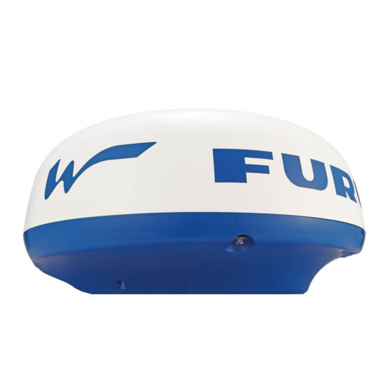
- Page 1 OPERATOR'S MANUAL RADAR SENSOR DRS4W Model www.furuno.com...
- Page 2 How to discard a used battery Some FURUNO products have a battery(ies). To see if your product has a battery, see the chapter on Maintenance. Follow the instructions below if a battery is used. Tape the + and - terminals of battery before disposal to prevent fire, heat generation caused by short circuit.
-
Page 3: Safety Information
SAFETY INFORMATION Read these safety instructions before installing or operating the equipment. Indicates a potentially hazardous situation which, if not avoided, WARNING can result in serious injury or death. Indicates a potentially hazardous situation which, if not avoided, CAUTION can result in minor or moderate injury. Prohibitive Action Mandatory Action Warning, Caution... - Page 4 WARNING LABEL NOTICE A warning label is attached to the sensor. Do not remove the label. If the label is missing or damaged, contact a FURUNO agent or dealer Do not expose the radar sensor to about replacement. strong water jets.
-
Page 5: Table Of Contents
TABLE OF CONTENTS FOREWORD ........v MAINTENANCE, TROUBLESHOOTING....8 OPERATION ......... 1 2.1 Maintenance .......8 1.1 System Overview ......1 2.2 Replacement of Fuse....8 1.2 How to Start, Stop the System ..1 2.3 Troubleshooting ......9 1.3 Transmit, Standby .......2 2.4 Error Messages......9 1.4 Display Layout......2 2.5 Replacement of Magnetron..9 1.5 Touch Screen Operations ...3... -
Page 6: Foreword
Congratulations on your choice of the and/or bearing direction. FURUNO RADAR SENSOR DRS4W. • Automatic adjustment of sea clutter (ech- Since 1948, FURUNO Electric Company has oes from waves), gain, noise and interfer- enjoyed an enviable reputation for innovative ence. -
Page 7: Operation
After the completion of the preheat- ing, the STBY display appears. To deactivate the system, disconnect the ra- dar sensor from the power source. Note: To connect an iOS terminal to another DRS4W, reset the application first. -
Page 8: Transmit, Standby
1. OPERATION Transmit, Standby When you don’t need the radar, set it to stand- by to extend the life of the magnetron. Tap the [STBY-TX] Note: The radar application is set to standby icon at the top right when you switch to another application, or corner on the screen there is no operation for one minute. -
Page 9: Touch Screen Operations
1. OPERATION Touch Screen Operations The table below shows all the basic touch screen operations. Operation Action Operation Action • Open, close Drag • Move the cur- menus. sor.* • Operate vari- • Move slider bar ous buttons. in menus. •... -
Page 10: How To Adjust The Screen Tone
1. OPERATION How to Adjust the How to Reduce Screen Tone Rain Clutter The screen tone (brightness) can be adjusted The antenna picks up rain to suit lighting conditions. Open the menu clutter (rain, snow, or hail) in the same manner as normal then tap the ( ) icon. -
Page 11: How To Off Center The Display
1. OPERATION 1.12 Echo Stretch On long ranges, target echoes tend to shrink, making them difficult to see. To enhance tar- get video on long ranges, use the echo stretch Bearing, feature to lengthen echoes in the bearing range to and/or range direction. -
Page 12: Echo Color
1. OPERATION 1.14 Echo Color 1.17 Settings Menu Echoes can be shown in yellow, green, or The [Settings] menu contains items that once multicolor. Multicolor paints each radar echo preset do not require frequent adjustment. in a color according to its strength, in red, yel- Open the menu then tap the ( ) icon to open low or green, corresponding to strong, medi- the [Settings] menu. - Page 13 1. OPERATION Initial Settings menu Units > Tune Initialize [Units]: Select the unit of range measure- ment, nm or km. [Tune Initialize]: Automatically tune the radar receiver. See the chapter on installation. Installation Settings menu The items in this menu are mainly intended for the serviceman.
-
Page 14: Maintenance, Troubleshooting
MAINTENANCE, TROUBLESHOOTING WARNING DO NOT OPEN THE SENSOR. Electrical shock hazard There are no user-serviceable parts inside. Only qualified personnel are allowed to work inside the equipment. Maintenance Replacement of Fuse Regular maintenance is important for good performance. Check the points mentioned be- The 5A fuse (Type: FGBO 250V 5A PBF, low every 3 to 6 months to keep the radar sen- Code No.: 000-155-840-10) in the fuse holder... -
Page 15: Troubleshooting
2. MAINTENANCE, TROUBLESHOOTING Troubleshooting Error Messages The table below provides simple trouble- Error messages are shown to alert you to ra- shooting procedures that the user can follow dar sensor problems. The table below shows to restore normal operation. If you cannot re- the error messages and accompanying mes- store normal operation, contact your dealer sage numbers and check points. -
Page 16: Self Test
2. MAINTENANCE, TROUBLESHOOTING Self Test The self test is for use by the service techni- cian to check the equipment. However, the user can do the test to support the service technician. 1. Open the menu then tap the ( ) icon. -
Page 17: Installation
INSTALLATION Equipment List Name Type Code No. Remarks Standard supply Radar Sensor RSB-126-103 Installation CP03-35800 000-024-974 Select Power cable assy., 10 m Materials CP03-35810 000-024-975 Power cable assy., 15 m CP03-35820 000-024-976 Power cable assy., 20 m CP03-35830 000-024-977 Power cable assy., 30 m CP03-35701 001-265-920 - Hex bolt*(M10×25), 4 pcs. -
Page 18: How To Install The Radar Sensor
3. INSTALLATION Radar sensor Radar sensor Radar sensor Radar sensor Installation on a sailboat Installation on a powerboat Typical installation on a sailboat, power boat Strong signal area Strong signal area Weak signal 60° area Strong signal 45° area Weak signal Weak signal area area... - Page 19 3. INSTALLATION 2. Construct a platform (steel or aluminum) Guidelines for laying the power cable referring to the outline drawing and the • The connectors must not strike any part of mounting template. Fasten the platform to the vessel by wind, etc. the mounting location.
- Page 20 3. INSTALLATION Installation with the radome mount How to fasten the bracket to the mast The optional radome mount lets you fasten 1. Drill eight holes of 6.5 mm diameter in the the radar sensor to a mast on a sailboat. mast and fix the bracket with eight stain- less steel rivets (local supply) of 6.4 mm Name, Type: Radome Mount, OP03-209...
-
Page 21: How To Set Up The Radar Sensor
3. INSTALLATION How to Set up the 3.4.2 Heading, timing adjustment Radar Sensor How to open the Installation Settings Before you can set up and use the radar sen- menu sor, download and install the free application [Marine Radar] from the App Store. The appli- To adjust the heading or timing, you must first cation is common to both the iPad and the open the [Installation Settings] menu. - Page 22 3. INSTALLATION Heading alignment 3. Visually identify a suitable target (for ex- ample, ship or buoy) at a range between You have mounted the radar sensor facing 0.125 to 0.25 miles. straight ahead in the direction of the bow. 4. Point your boat’s bow directly toward the Therefore, a small but conspicuous target target selected at step 3.
-
Page 23: Range Unit
3. INSTALLATION 3.4.5 Sector blank 3. Tap the menu navigation buttons ( to select [Timing Adjustment]. A sector blank is an area on the radar display where no radar echoes appear because an Heading Align (0~359) obstruction near the radar sensor (for exam- ple, a mast) blocks reception within that area. -
Page 24: Appendix 1 Menu Tree
APPENDIX 1 MENU TREE Color Color Picture Picture Settings Settings menu menu menu menu menu menu Display Settings Full Screen (Off, On) Range Ring (Off, On) Own Ship Mark (Off, On) Initial Settings Units (nm, km) Tune Initialize Installation Settings (Antenna Rotation, Jamming, On Time, Tx Time, Video Contrast, Factory Default) Self Test Operation Guide... -
Page 25: Latory Information
APPENDIX 2 RADIO REGULATORY INFORMATION Wireless interoperability This product is designed to be interoperable with any wireless LAN product that is based on direct sequence spread spectrum (DSSS) and orthogonal frequency division multiplexing (OFDM) radio technology and to comply with the following standards. •... - Page 26 APPENDIX 2 RADIO REGULATORY INFORMATION USA-Federal Communications Commission This equipment has been tested and found to comply with the limits for a Class B digital device, pursuant to Part 15 of FCC Rules. These limits are designed to provide reasonable protection against harmful interference in a residential installation.
- Page 27 APPENDIX 2 RADIO REGULATORY INFORMATION Canada-Industry Canada (IC) This device complies with RSS 210 of Industry Canada.Operation is subject to the following two conditions: (1) This device may not cause interference, and (2) This device must accept any interference, including interference that may cause undesired op- eration of this device.
-
Page 28: Specifications
FURUNO DRS4W SPECIFICATIONS OF RADAR SENSOR DRS4W RADIATOR Antenna type Patch array antenna Antenna length 15-inch Horizontal beam width 7.2° (3 dB) Vertical beam width 25° (3 dB) Gain 20 dBi or more Sidelobe attenuation -18 dB (within ±20°), -20 dB (±20° or more) - Page 29 PACKING LIST 03HN-X-9851 -3 DRS4W N A M E DESCRIPTION/CODE № O U T L I N E Q'TY ユニット UNIT レーダーセンサー RSB-126-103 RADAR SENSOR 000-024-973-00 予備品 SPARE PARTS 予備品 SP03-17801 SPARE PARTS 001-265-910-00 工事材料 INSTALLATION MATERIALS 工事材料 CP03-35701 INSTALLATION MATERIALS 001-265-920-00 図書...
- Page 32 When a claim is made, FURUNO has a right to choose whether with other electronic devices. The imported product may also be to repair the product or replace it.
- Page 33 24 months from installation date provided the work is done by Furuno U.S.A., Inc. or an AUTHORIZED Furuno dealer during normal shop hours and within a radius of 50 miles of the shop location.
- Page 36 The paper used in this manual is elemental chlorine free. ・FURUNO Authorized Distributor/Dealer 9-52 Ashihara-cho, Nishinomiya, 662-8580, JAPAN A : MAR 2014 Printed in Japan All rights reserved. Pub. No. OME-36360-A (DAMI ) DRS4W 0 0 0 1 7 8 9 4 6 1 0...
Need help?
Do you have a question about the DRS4W and is the answer not in the manual?
Questions and answers