Table of Contents
Advertisement
Quick Links
Installation Manual
RADAR SENSOR
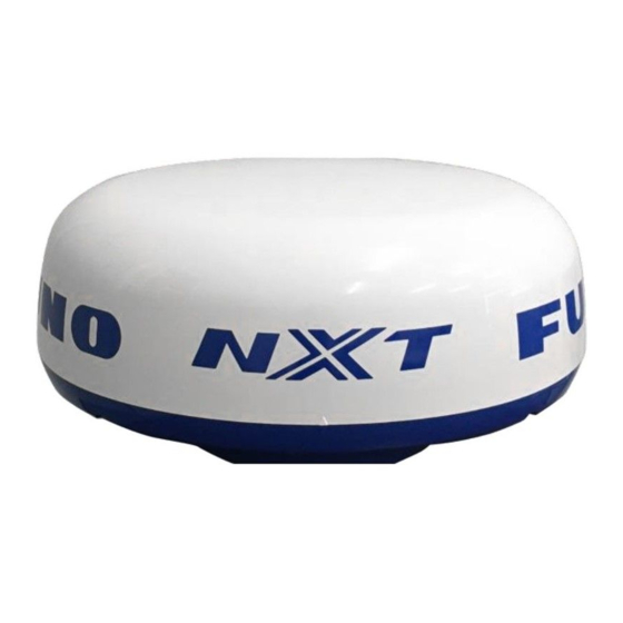
DRS2D-NXT/DRS4D-NXT
Model
(Product name: SOLID STATE DOPPLER RADAR)
SAFETY INSTRUCTIONS ................................................................................................ i
SYSTEM CONFIGURATION .......................................................................................... iii
EQUIPMENT LISTS........................................................................................................ iv
FOREWORD .................................................................................................................... v
1. INSTALLATION.......................................................................................................... 1
1.1 Installation Considerations....................................................................................................1
1.2 Installation of the Radar Sensor............................................................................................3
1.3 Wiring....................................................................................................................................7
2. INITIAL SETUP........................................................................................................... 8
2.1 Check Points After Installation ..............................................................................................8
2.2 Initial Setup ...........................................................................................................................8
3. MAINTENANCE, TROUBLE- SHOOTING............................................................... 15
3.1 Maintenance .......................................................................................................................15
3.2 Replacement of Fuse..........................................................................................................15
3.3 Troubleshooting ..................................................................................................................16
3.4 Life of Parts.........................................................................................................................16
APPENDIX 1 RADIO REGULATORY INFORMATION ............................................AP-1
SPECIFICATIONS ..................................................................................................... SP-1
PACKING LISTS ......................................................................................................... A-1
OUTLINE DRAWINGS ................................................................................................ D-1
INTERCONNECTION DIAGRAMS.............................................................................. S-1
www.furuno.com
All brand and product names are trademarks, registered trademarks or service marks of their respective holders.
Advertisement
Table of Contents

Related Manuals for Furuno DRS2D-NXT


Summary of Contents for Furuno DRS2D-NXT
-
Page 1: Table Of Contents
Installation Manual RADAR SENSOR DRS2D-NXT/DRS4D-NXT Model (Product name: SOLID STATE DOPPLER RADAR) SAFETY INSTRUCTIONS ....................i SYSTEM CONFIGURATION ..................iii EQUIPMENT LISTS......................iv FOREWORD ........................v 1. INSTALLATION......................1 1.1 Installation Considerations....................1 1.2 Installation of the Radar Sensor....................3 1.3 Wiring............................7 2. -
Page 2: Safety Instructions
SAFETY INSTRUCTIONS The installer of the equipment must read the safety instructions before attempting to install the equipment. Indicates a potentially hazardous situation which, if not avoided, WARNING could result in death or serious injury. Indicates a potentially hazardous situation which, if not avoided, CAUTION can result in minor or moderate injury. - Page 3 - Name: FURUNO (UK) LTD. - Address: West Building Penner Road Havant Hampshire PO9 1QY, U.K. Program No. ・0359360-01.** ** denotes minor modifications. CE declaration With regards to CE declarations, please refer to our website (www.furuno.com), for further information about RoHS conformity declarations.
-
Page 4: System Configuration
SYSTEM CONFIGURATION RADAR SENSOR DRS2D-NXT/ DRS4D-NXT Cable Assembly Power/LAN cable CP03-36400/ CP03-36410/ CP03-36420/ CP03-36430 (10/15/20/30 m, select the length when purchasing.) Switch Multi Function Display TZTL12F/TZTL15F/TZT2BB TZT9/TZT14/TZTBB TZT9F/TZT12F/TZT16F/TZT19F Power supply 12/24 VDC : Standard supply : Local supply Software upgrade to version 8.01 or later is required. -
Page 5: Equipment Lists
EQUIPMENT LISTS Standard supply Name Type Code No. Remarks Radar Sensor RSB-135-115 000-029-247 For DRS4D-NXT RSB-147-133 000-038-279 For DRS2D-NXT Installation Materials CP03-37001 001-426-200 Spare Parts SP03-19401 001-513-730 Fuses Optional supply Name Type Code No. Remarks Radome Mount OP03-208 001-078-340 Retrofit Kit... -
Page 6: Foreword
FOREWORD General Information about DRS2D-NXT/DRS4D-NXT Note: Most of the figures in this manual are based on the DRS4D-NXT. Layouts may be slightly different if you have the DRS2D-NXT. ™ • TARGET ANALYZER function* displays targets that are moving and getting close to own ship in red and other targets in different colors. -
Page 7: Installation
INSTALLATION Installation Considerations NOTICE Do not apply paint, anti-corrosive sealant or contact spray to coating or plastic parts of the equipment. Those items contain organic solvents that can damage coating and plastic parts, especially plastic connectors. • Do not paint the radome, radar wave emission may be affected. •... - Page 8 (upright). Consideration for selecting a location for installation (multiple radars) • In case multiple radars are installed on a ship, DO NOT install the DRS2D-NXT/ DRS4D-NXT within the range of beam area emitted from other radar(s). Use the il- lustration below for reference when selecting a suitable location for installation.
-
Page 9: Installation Of The Radar Sensor
1. INSTALLATION Installation with the radiotelephone equipment • Install the radome away from radiocommunication antennas (SSB, VHF, Inmarasat) and GPS antenna to prevent radar interference. • Install the radome away from the radiotelephone equipment so that electrical noise does not affect the radiotelephone equipment. Cable routing •... - Page 10 1. INSTALLATION STERN Align bow mark (Δ) on Power/LAN cable (1 m) radome with ship’s bow. Platform Flat washer Holes drilled referring to the outline drawing and the mounting template in this manual. Spring washer Hex bolt (M10×25) 1. Set the supplied mounting template to the mounting location, then drill four fixing holes in the mounting location.
- Page 11 1. INSTALLATION • If the cable is passed through a mast on a sailboat, be sure the cable does not touch ropes (sheet, halyard, etc.). • Do not let the cable touch the hull. • The cable must be located where no tension is applied to the connectors. To prevent tension, create a loop in the cable close to the sensor and tie the loop with cable ties, as in the figure below.
- Page 12 1. INSTALLATION Installation with the radome mount The optional radome mount lets you fasten the radar sensor to a mast on a sailboat. Name, Type: Radome Mount, OP03-208 Code No.: 001-078-340 Name Type Code No. Mounting plate 03-018-9001-0 100-206-740-10 Support plate (1) 03-018-9002-3 100-206-753-10 Support plate (2)
-
Page 13: Wiring
1.3.1 Power requirement The DRS2D-NXT/DRS4D-NXT requires either 12 VDC or 24 VDC power. Connect the red cable to the positive terminal of ship‘s battery; the blue cable to the negative ter- minal. The black cable is a shielding cable for grounding. -
Page 14: Initial Setup
• Turning the power on and initial setup Mechanical checks Check below points before switching on the DRS2D-NXT/DRS4D-NXT. • All washers are in place and bolts are fully fastened. • All connections are secure and LAN connector of the cable assembly is connected to the multi function display device. - Page 15 2. INITIAL SETUP 5. Referring to the tables below, set up the radar. [Radar] menu - [Radar Initial Setup] Menu item Description [Antenna Rotation] Select the speed of antenna rotation. [Antenna Heading Align] See "How to align the antenna heading" on page 9. [Main Bang Suppression] If main bang appears at the screen center, slide the circle icon so that the main bang disappears, while watching the...
- Page 16 2. INITIAL SETUP Correct bearing (relative to heading) Target Direction of bow mark Apparent position of target Antenna oriented to port Picture appears deviated clockwise. Apparent position of target Target Direction of bow mark Correct bearing (relative to heading) Antenna oriented to starboard Picture appears deviated counterclockwise.
- Page 17 2. INITIAL SETUP 2.2.2 Initial setup for TZT9/TZT14/TZTBB 1. Press the Home key (or tap the Home icon). 2. Select [Menu] on the menu icon bar to open the main menu. 3. Select [Radar]. 4. Select [Radar Source] on the [Menu Radar] sub menus, then select the radar type connected.
- Page 18 2. INITIAL SETUP Menu item Description [Enable Sector Up to two sectors may be selected for blanking (no transmission). Blanking] Select [ON] to enable this feature. Set the start and end angles (0° to 359°). [Enable Sector 2 Blanking] [Antenna Height] Select the height of the antenna above the waterline.
- Page 19 2. INITIAL SETUP How to align the antenna heading You have mounted the antenna unit facing straight ahead in the direction of the bow. Therefore, a small but conspicuous target dead ahead visually should ap- pear on the heading line (zero degrees). In practice, you will probably observe some small bearing error on the display be- cause of the difficulty in achieving accurate initial positioning of the antenna unit.
- Page 20 2. INITIAL SETUP For TZTBB, you can also control the range in the operation as follows. Tap the radar scale box at the bottom left-hand corner of the screen to display the slider bar. Drag the circle icon to set the range scale. Zoom in Slider bar Current...
-
Page 21: Maintenance, Trouble- Shooting
MAINTENANCE, TROUBLE- SHOOTING WARNING DO NOT OPEN THE SENSOR. Electrical shock hazard There are no user-serviceable parts inside. Only qualified personnel are allowed to work inside the equipment. Maintenance Regular maintenance is important for good performance. Check the points mentioned below every 3 to 6 months to keep the radar sensor in good working order. -
Page 22: Troubleshooting
3. MAINTENANCE, TROUBLE- SHOOTING Troubleshooting The table below provides simple troubleshooting procedures to restore normal opera- tion. If you cannot restore normal operation, contact your dealer for advice. Trouble Remedy The radar type does not appear • Check if the cable assembly is connected to the on the multi function display de- power source and the power source is on. -
Page 23: Appendix 1 Radio Regulatory Information
APPENDIX 1 RADIO REGULATORY INFORMATION USA-Federal Communications Commission (FCC) This device complies with part 15 of the FCC Rules. Operation is subject to the following two conditions: (1) This device may not cause harmful interference, and (2) This device must accept any interference received, including interference that may cause undesired operation. -
Page 24: Specifications
FURUNO DRS2D-NXT SPECIFICATIONS OF RADAR SENSOR DRS2D-NXT RADIATOR Antenna type Patch array antenna Antenna length 17-inch Horizontal beam width 5.2° typical (-3dB) RezBoost effective beam width* 2.0° to 3.9° *: RezBoost provides better echo resolution, in a manner similar to adjusting the beam width. - Page 25 FURUNO DRS4D-NXT SPECIFICATIONS OF RADAR SENSOR DRS4D-NXT RADIATOR Antenna type Patch array antenna Antenna length 22-inch Horizontal beam width 3.9° typical (-3dB) RezBoost effective beam width* 2.0° to 3.9° *: RezBoost provides better echo resolution, in a manner similar to adjusting the beam width.
-
Page 26: Packing Lists
PACKING LIST 03HU-X-9851 -1 RSB-127-120 N A M E DESCRIPTION/CODE № O U T L I N E Q'TY ユニット UNIT 空中線部 RSB-127-120 ANTENNA UNIT 000-033-121-00 工事材料 INSTALLATION MATERIALS 工事材料 CP03-35701 INSTALLATION MATERIALS 001-351-480-00 図書 DOCUMENT 型紙 E32-01314-* TEMPLATE 000-178-948-1* (略図の寸法は、参考値です。 DIMENSIONS IN DRAWING FOR REFERENCE ONLY.) C3666-Z01-B... - Page 27 PACKING LIST 03HR-X-9851 -1 DRS4D-NXT-J/E N A M E DESCRIPTION/CODE № O U T L I N E Q'TY ユニット UNIT レーダーセンサー RSB-135-115 RADAR SENSOR 000-029-247-00 予備品 SPARE PARTS 予備品 SP03-19401 SPARE PARTS 001-513-730-00 工事材料 INSTALLATION MATERIALS 工事材料 CP03-37001 INSTALLATION MATERIALS 001-426-200-00 図書...
- Page 28 001-426-200-00 03HR-X-9401 CODE NO. TYPE CP03-37001 工事材料表 INSTALLATION MATERIALS 数量 番 号 名 称 略 図 型名/規格 用途/備考 Q'TY OUTLINE NAME DESCRIPTIONS REMARKS ミガキ平座金 M10 SUS304 FLAT WASHER CODE 000-167-232-10 バネ座金 M10 SUS304 SPRING WASHER CODE 000-167-233-10 六角スリワリ ボルト M10X25 SUS304 HEX.BOLT (SLOTTED HEAD) CODE...
- Page 29 SETS PER SHIP NO. SPARE PARTS LIST FOR VESSEL QUANTITY REMARKS/CODE NO. DWG. NO. NAME OF ITEM WORKING OUTLINE PART TYPE NO. SPARE ヒューズ BLADE FUSE FRU-60V-FU-5A 000-194-913-10 MFR'S NAME FURUNO ELECTRIC CO.,LTD. DWG NO. (略図の寸法は、参考値です。 DIMENSIONS IN DRAWING FOR REFERENCE ONLY.)...
- Page 33 When a claim is made, FURUNO has a right to choose whether with other electronic devices. The imported product may also be to repair the product or replace it.
- Page 34 24 months from installation date provided the work is done by Furuno U.S.A., Inc. or an AUTHORIZED Furuno dealer during normal shop hours and within a radius of 50 miles of the shop location.
- Page 35 Цялостният текст на ЕС декларацията за съответствие може да се намери на следния интернет адрес: Spanish Por la presente, Furuno Electric Co., Ltd. declara que el tipo de equipo (ES) radioeléctrico arriba mencionado es conforme con la Directiva 2014/53/UE. El texto completo de la declaración UE de conformidad está disponible en la dirección Internet siguiente:...
- Page 36 O texto integral da declaração de conformidade está disponível no seguinte endereço de Internet: Romanian Prin prezenta, Furuno Electric Co., Ltd. declară că menționat mai sus tipul de (RO) echipamente radio este în conformitate cu Directiva 2014/53/UE. Textul integral al declarației UE de conformitate este disponibil la următoarea adresă...
- Page 40 ・FURUNO Authorized Distributor/Dealer 9-52 Ashihara-cho, Nishinomiya, 662-8580, JAPAN A : DEC 2015 Printed in Japan All rights reserved. F : APR . 04, 2022 Pub. No. IME-36490-F (TASU ) DRS4D-NXT/DRS2D-NXT 0 0 0 1 9 1 0 8 2 1 5...
Need help?
Do you have a question about the DRS2D-NXT and is the answer not in the manual?
Questions and answers