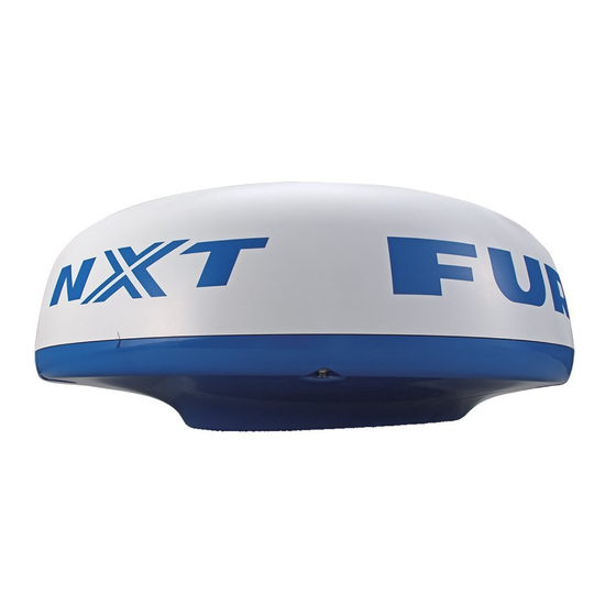
Furuno DRS4D Installation Manual

Furuno DRS4D Installation Manual

Radar sensor
Hide thumbs Also See for DRS4D:

Advertisement

Quick Links

DRS4A/DRS6A/DRS12A/DRS25A
SAFETY INSTRUCTIONS ............................................................................ i
SYSTEM CONFIGURATION ....................................................................... ii
EQUIPMENT LISTS.................................................................................... iv
1. MOUNTING ............................................................................................ 1
1.1
Mounting Considerations..............................................................................................1
1.2
Mounting Procedure for DRS2D/4D .............................................................................2
1.3
Mounting Procedure for DRS4A/6A/12A/25A...............................................................3
1.4
Mounting of Power Supply Unit ....................................................................................8
2. WIRING ................................................................................................ 11
2.1
Wiring inside DRS2D/4D ............................................................................................15
2.2
Wiring inside DRS4A/6A/12A/25A..............................................................................19
2.3
Wiring of Power Supply Unit.......................................................................................23
SPECIFICATIONS ................................................................................. SP-1
PACKING LISTS...................................................................................... A-1
OUTLINE DRAWINGS............................................................................. D-1
INTERCONNECTION DIAGRAMS.......................................................... S-1
Installation Manual
RADAR SENSOR
Model
www.furuno.com
DRS2D/DRS4D/

Advertisement

Table of Contents
loading

Summary of Contents for Furuno DRS4D

  • Page 1: Table Of Contents

    Installation Manual RADAR SENSOR DRS2D/DRS4D/ Model DRS4A/DRS6A/DRS12A/DRS25A SAFETY INSTRUCTIONS ................i SYSTEM CONFIGURATION ............... ii EQUIPMENT LISTS..................iv 1. MOUNTING .................... 1 Mounting Considerations....................1 Mounting Procedure for DRS2D/4D ................2 Mounting Procedure for DRS4A/6A/12A/25A...............3 Mounting of Power Supply Unit ..................8 2. WIRING ....................11 Wiring inside DRS2D/4D ....................15...
  • Page 3: Safety Instructions

    This Serious injury or death can result if the is possible - Ask your FURUNO representive or power is left on or is applied while the dealer to provide this feature. equipment is being installed.
  • Page 4: System Configuration

    SYSTEM CONFIGURATION DRS2D/4D/4A/6A/12A RADAR SENSOR DRS2D/DRS4D RADAR SENSOR DRS4A/DRS6A/DRS12A NMEA 2000 Equipment Power Supply Unit* Power Supply Unit* NMEA 2000 PSU-017* PSU-017* Equipment 12-24 VDC Power Supply Unit* Power Supply Unit* 12-24 VDC PSU-012 PSU-012 Multi Function Display Multi Function Display...
  • Page 5 Importer in Europe The following concern acts as our importer in Europe, as defined in DECISION No 768/2008/EC. - Name: FURUNO EUROPE B.V. - Address: Ridderhaven 19B, 2984 BT Ridderkerk, The Netherlands Program No. • 0359235-01.**...
  • Page 6: Equipment Lists

    For DRS12A, 1795 mm, w/CP03-32601 XN12A-RSB-118-095 For DRS25A, 1255 mm, w/CP03- 32601 XN13A-RSB-118-095 For DRS25A, 1795 mm, w/CP03- 32601 DRS2D Radome, 2 kW, w/CP03-32101 DRS4D Radome, 4 kW, w/CP03-32101 Power Supply PSU-013 For DRS25A, w/SP03-16101 and Unit CP03-32700 Installation CP03-32101 001-025-270...
  • Page 7 For DRS4A/6A, φ10 NMEA2000 cable OP03-206 001-035-290 For DRS25A, φ10 NMEA2000 cable Resister Assy OP03-204 001-025-300 For NMEA2000 connection with a unit Radome OP03-208 001-078-340 For DRS4D Mount OP03-209 001-078-350 For DRS2D Joint Box* TL-CAT-012 000-167-140-10 For LAN cable extension LAN Cable MOD-Z072-020+...
  • Page 8: Mounting

    1. MOUNTING NOTICE Do not apply paint, anti-corrosive sealant or contact spray to coating or plastic parts of the equipment. Those items contain organic solvents that can damage coating and plastic parts, especially plastic connectors. Mounting Considerations • The radar sensor is generally installed either on top of the wheelhouse or on the radar mast on a suitable platform.
  • Page 9: Mounting Procedure For Drs2D/4D

    Radar sensor Radar sensor Radar sensor Radar sensor For DRS2D/4D Mounting Procedure for DRS2D/4D 1. Remove mounting hardware at the bottom of the radar sensor, four each of hex bolts (M10x20), spring washers and flat washers. Save the spring washers and flat washers to use them to fix the radome base to the platform, at step 3.
  • Page 10: Mounting Procedure For Drs4A/6A/12A/25A

    3. Use the hex bolts*, flat washers and spring washers removed at step 1, and fasten the radome base to the platform. The torque should be between 19.6-24.5N m. *If the thickness of the platform is 6-10 mm, use M10x25 bolts (supplied). For thicker platform, use locally supplied bolts.
  • Page 11 5. Coat the hex bolts (4 pcs.) with silicone sealant. Fasten the antenna radiator to the radiator bracket with the hex bolts, flat washers and spring washers supplied with the radiator Then, apply silicone sealant around the junction part between the radiator and bracket. 6.
  • Page 12 2. Lay the radar sensor on the mounting platform, orienting it as shown below. (The hinges must face toward the stern.) STERN Hinge CAUTION Do not lift the radar sensor by the radiator; lift it by the housing. The radiator may be damaged. 3.
  • Page 13 4. Pass flat washers (M12, supplied), spring washers (M12, supplied) and nuts (M12, supplied) onto hex. bolts. Fasten by tightening nuts. Do not fasten by tightening the hex. bolts; seal washers may be damaged. Seal washer Antenna unit Rubber mat Mounting platform Silicone...
  • Page 14 Using inside fixing holes of the sensor housing If this radar is replacing a FURUNO radar whose mounting dimensions are the same as this one (140 x 150 mm), it may be possible to use its mounting platform. This method requires removal of the RF unit from the radar sensor to access inside fixing holes.
  • Page 15: Mounting Of Power Supply Unit

    Mounting of Power Supply Unit 1.4.1 PSU-013 (for DRS25A)/PSU-012 (Option) For combinations shown below, the optional power supply unit PSU-012 or PSU-017 is necessary. The PSU-013 is required for any DRS25A installation DRS2D/4D DRS4A DRS12A DRS6A MFD8 PSU-012 PSU-012 PSU-012 MFD12 PSU-012 MFDBB...
  • Page 16 Mounting When selecting a location, keep in mind the following points. Fix the power supply unit on the desktop or bulkhead with four self-tapping screws (4x20, supplied). • Location is dry, well ventilated. • Make sufficient maintenance space. • Installed within 2, 5 or 10 m (2 and 10 m: optional supply) from the multi function display. Self-tapping screw (4x20, 4 pcs.) Note: When you install the unit on the bulkhead, fix the unit with the following direction.
  • Page 17 1.4.2 PSU-017 (option) A power supply unit is required when you connect a radar sensor. The PSU-017 is available in the combination of DRS2D/4D and TZT9/14/BB. Use the PSU-012 or PSU-013 in all other combina- tions. LED for the operation check: Lights in green when the unit outputs 48 VDC.
  • Page 18: Wiring

    Before connecting or disconnecting the NMEA2000 cable, turn off the radar sensor. The sensor may become damaged if the power is not turned off. Wiring for DRS2D/4D/4A/6A/12A without PSU-012 RADAR SENSOR DRS2D/DRS4D RADAR SENSOR DRS4A/DRS6A/DRS12A NMEA2000 cable M12-05BFFM (φ6) or Two-way cable CB-05BFFM (φ10)
  • Page 19 Wiring for DRS2D/4D/4A/6A/12A with PSU-012 Radar Sensor DRS2D/DRS4D Radar Sensor DRS4A/DRS6A/DRS12A NMEA2000 cable M12-05BFFM (ø6) or Two-way cable CB-05BFFM (ø10) NMEA2000 MOD-ASW0001 Equipment (10/15/20/30 m) NMEA2000 Equipment NMEA2000 cable M12-05BFFM (ø6) or (LAN) (Power) CB-05BFFM (ø10) Power Supply Unit PSU-012...
  • Page 20 Wiring for DRS25A RADAR SENSOR DRS25A NMEA2000 cable M12-05BFFM (ø6) or CB-05BFFM (ø10) NMEA2000 Equipment Two-way cable MOD-ASW0002 cable (POWER) (10/15/20/30 m) (LAN) Power cable VL3P-VV-S2X2C-AA050 (Supplied with PSU-013) Power Supply Unit PSU-013 LAN cable 12-24 VDC MOD-2072-050 Ground wire : Standard Supply (Local supply, IV-2sq) To Multi Function Display BlackBox...
  • Page 21 2. Connect wires to the NMEA connector consulting the label on the connector. NMEA2000 connector (in the sensor) Note: This fabrication is not necessary when the external terminators are attached as below. NMEA2000 equipment DRS2D/DRS4D DRS4A/DRS6A/DRS12A Backbone cable External External terminator 1...
  • Page 22: Wiring Inside Drs2D/4D

    Wiring inside DRS2D/4D Two-way cable connection 1. Unfasten three screws at the bottom of the mounting base to remove the fixing plate for the gasket. Fixing plate (for gasket) 2. Remove the gasket, and pass the two-way cable MOD-ASW0001. 3. Fasten the shield of the cable (power) with the cable clamp in the radar sensor, and connect the connector of cable (power) to the power terminal.
  • Page 23 6. Slide the gasket on cables so that the amount of cable above the gasket is lower than the RF chassis. This height should be lower than the RF unit when installed to the bottom of the sensor. Cable Gasket RF unit Gasket Note: If the two-way cable touches the platform near the mounting base, wind vinyl tape around...
  • Page 24 Shield CB-05BFFM cable Fasten the cable tie (supplied) within 15 mm from the end of vinyl sheath. Wind vinyl tape. (supplied) CB-05BFFM cable 15 (Area fastened with the cable clamp) Fabrication of CB-05BFFM cable 3. Insert wires of cable M12-05BFFM (φ6) or CB-05BFFM (φ10) to the NMEA connector inside the radar sensor, consulting the label on the connector for location.
  • Page 25 4. Push LAN and POWER cables of the two-way cable and cable M12-05BFFM (φ6) or CB- 05BFFM (φ10) into the slits of the gasket inside the mounting base. Depending on the NMEA2000 cable used, replace the gasket as shown below. Cable type M12-05BFFM (φ6) CB-05BFFM (φ10)
  • Page 26: Wiring Inside Drs4A/6A/12A/25A

    Wiring inside DRS4A/6A/12A/25A Two-way cable connection If you have no NMEA2000 equipment to connect, use the MOD-ASW0001 cable (standard sup- ply). 1. Open the radar sensor cover by loosening four bolts, and fix the stay for safety purpose. 2. Unfasten four bolts to detach the plate, gasket, washer and lid. Discard the lid at the bottom of the hole for the gasket.
  • Page 27 5. Attach the LAN cable of the two-way cable to the LAN terminal in the radar sensor. Fix the power cable at the foil part with this cable clamp. Power cable White Black Power terminal LAN cable RF unit LAN terminal DRS4A/6A/12A Fix the power cable at the copper foil part with this cable clamp.
  • Page 28 7. Slide the gasket on cables so that the amount of cable above the gasket is lower than the RF chassis. This height should be lower than the RF unit when installed to the bottom of the sensor. Cable RF unit Gasket Gasket Washers...
  • Page 29 the crimp-on lug (pre-attached at the bottom of the chassis) to the drain wire, and fasten it with the screw shown below. view NMEA connector NMEA connector Crimp-on lug Drain wire Fasten the drain wire with this screw. NMEA cable RF unit 5.
  • Page 30: Wiring Of Power Supply Unit

    Wiring of Power Supply Unit 2.3.1 Wiring inside power supply unit PSU-013 (for DRS25A) 1. Detach the body cover by hand. 2. Loosen six pan head screws (M3x8) and slide the shield cover upward to remove it. 3. Unfasten four pan head screws (M14x10) to remove two cable clamps. Body cover Shield cover Pan head screws...
  • Page 31 2.3.2 Wiring inside power supply unit PSU-012 (Option) 1. Detach the body cover by hand. 2. Loosen six pan head screws (M3x8) and slide the shield cover upward to remove it. 3. Unfasten two pan head screws (M4x12) to remove the cable clamp. Body cover Shield cover Pan head screw...
  • Page 32 2.3.3 Wiring the power supply unit PSU-017 (option, for DRS2D/4D) Connect the power cable and MOD-ASW0001 cables to appropriate connectors of the power sup- ply unit as shown below. When you connect the power cable to ship’s mains, pass through the disconnecting device (breaker, etc.).
  • Page 33 3. Confirm that the LED on the board is OFF, and then replace the fuse. Note: DO NOT change the fuse if the LED is ON; this indicates high voltage is present. Fuse F2 (1.5A 125V) Fuse F1 (7A 125V) 1: Brown (P48V) 2: Red (DC_N) 1: White (DC_P)
  • Page 34: Specifications

    -27 dB (within ±10°), -28 dB (±10° or more) Rotation 24/36/48 rpm RADAR FUNCTION TX frequency 9410±30 MHz, P0N Output power (nominal) DRS2D: 2.2 kW, DRS4D/4A: 4 kW, DRS6A: 6 kW, DRS12A: 12 kW DRS25A: 25 kW Duplexer Ferrite circulator with diode limiter Intermediate frequency 60 MHz...
  • Page 35 FURUNO DRS SERIES Maximum range DRS2D: 24 NM, DRS4D: 36 NM, DRS4A: 48 NM, DRS6A: 64 NM, DSR12A: 72 NM, DRS25A: 96 NM Minimum range 25 m Range resolution 20 m Bearing resolution DRS2D: 5.2°, DRS4D: 4°, DRS4A: 2.3°, DRS6A: 1.9°, DRS12A/25A: 1.9°...
  • Page 42 2/Apr/08 R.Esumi...
  • Page 43 28/Apr/08 R.Esumi...
  • Page 44   Y.NISHIYAMA 16/Oct/2012...
  • Page 49 When a claim is made, FURUNO has a right to choose whether with other electronic devices. The imported product may also be to repair the product or replace it.
  • Page 50 24 months from installation date provided the work is done by Furuno U.S.A., Inc. or an AUTHORIZED Furuno dealer during normal shop hours and within a radius of 50 miles of the shop location.
  • Page 52 (Elemental Chlorine Free) The paper used in this manual is elemental chlorine free. FURUNO Authorized Distributor/Dealer 9-52, Ashihara-cho, Nishinomiya, 662-8580, JAPAN A: JAN. 2008 All rights reserved. Printed in Japan F3: SEP. 16, 2016 Pub. No. IME-35670-F3 (ETMI) DRS2D/4D/4A-25A 00016745115...

Table of Contents