Furuno 1835 Installation Manual
Furuno marine radar user manual
Hide thumbs
Also See for 1835:
- Operator's manual (130 pages) ,
- Installation manual (48 pages) ,
- Quick manual (3 pages)
Table of Contents
Advertisement
Safety Instructions............................................................................................................. i
SYSTEM CONFIGURATION........................................................................................................ ii
Equipment Lists .................................................................................................................... iii
1.
How To Install The System..................................................................................... 1-1
1.1
Display Unit ............................................................................................................... 1-1
1.2
Antenna Unit For Model1835 .................................................................................. 1-3
1.3
Antenna Unit For Model1935/1945 ......................................................................... 1-9
2. CABLE CONNECTION ......................................................................................................... 2-1
2.1
Standard Connection ................................................................................................ 2-1
2.2
Data Signal Port ........................................................................................................ 2-2
3. HOW TO SET THE EQUIPMENT.......................................................................................... 3-1
3.1
How To Set The Language.......................................................................................... 3-1
3.2
How To Set The Purpose and Model .......................................................................... 3-2
3.3
How To Enter The Initial Settings ................................................................................ 3-3
4. OPTIONAL EQUIPMENT ...................................................................................................... 4-1
4.1
Arp Kit Arp-11 ........................................................................................................ 4-1
4.2
Connection Of Buzzer And/Or Remote Display .......................................................... 4-4
Packing ListS ...................................................................................................................... A-1
Outline DrawingS ............................................................................................................. D-1
Interconnection DiagramS ...........................................................................................S-1
All brand and product names are trademarks, registered trademarks or service marks of their respective holders.
Installation Manual
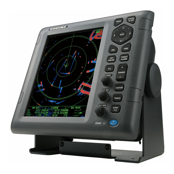
MARINE RADAR
MODEL1835/1935/1945
www.furuno.co.jp
Advertisement
Table of Contents

Related Manuals for Furuno 1835


Summary of Contents for Furuno 1835
- Page 1 Connection of Buzzer and/or Remote Display ... 4-4 PACKING LISTS ... A-1 OUTLINE DRAWINGS ... D-1 INTERCONNECTION DIAGRAMS ...S-1 All brand and product names are trademarks, registered trademarks or service marks of their respective holders. Installation Manual MARINE RADAR MODEL1835/1935/1945 www.furuno.co.jp...
- Page 3 Note: If the antenna unit is installed at a close distance in front of the wheel house, your administration may require halt of transmission within a certain sector of antenna revolution. This is possible - Ask your FURUNO representative or dealer to provide this feature. MODEL MODEL1835 MODEL1935 MODEL1945 0.30 m...
- Page 4 SYSTEM CONFIGURATIONS MODEL 1835 Antenna unit RSB-0071-057 Heading sensor Echo sounder GPS navigator AIS, etc. Echo sounder GPS navigator AIS, etc. : Basic configuration MODEL 1935 Antenna unit XN-10A RSB-0070/0073-064 Display unit RDP-152 CANCEL MENU HL OFF ENTER TARGET CENTER...
-
Page 5: Equipment Lists
EQUIPMENT LISTS Standard supply Name Type Display unit RDP-152 Antenna unit RSB-0071-057 XN10A-RSB-0070-064 XN10A-RSB-0073-064 XN12A-RSB-0070-059 XN12A-RSB-0073-059 Installation CP03-21800 materials CP03-21810 CP03-21820 CP03-21830 CP03-33000 CP03-33010 CP03-33020 CP03-33030 CP03-33040 CP03-32901 MJ-A3SPF0017-050ZC CP03-16901 CP03-18401 Accessories FP03-11601 Spare parts SP03-12200 Note: The name for MODEL1835, MODEL1935, MODEL1945 is shortened to M1835, M1935, M1945 in this manual. - Page 6 Optional supply Name Rectifier PR-62 RU-3423 External buzzer OP03-21 Cable assy. MJ-B24LPF0010-100+R MJ-B24LPF0010-200+R MJ-B24LPF0010-300+R MJ-A10SPFW0001+R MJ-A6SPF0007-100C MJ-A7SPF0007-050C ARP kit ARP-11 Mounting OP03-92 bracket Type Code No. 000-030-097 000-147-880-12 000-147-881-12 000-147-882-12 000-170-478-10 000-159-695-10 000-154-028-10 008-523-050 008-445-070 Comment For M1835 For M1935/1945 For remote display, 10 m For remote display, 20 m For remote display, 30 m...
-
Page 7: How To Install The System
Display Unit Select a location for the display unit by following the information shown below. • The unit is waterproof, but FURUNO recommends that you install the display unit in a cabinet. • Keep the unit away from direct sunlight. - Page 8 How to install the display unit in a console Follow the procedure shown below to install the display unit in a console. 1. Prepare a hole in the location whose dimensions are 274 (W) x 252 (H) mm. 2. Make four pilot holes. See the outline drawing at the back of this manual for additional infor- mation.
-
Page 9: Antenna Unit For Model1835
Antenna Unit for MODEL1835 How to select the location for the antenna unit When you select an installation location for the antenna unit, remember the following points. • Install the antenna unit on a solid location, for example radar arch or on a mast on a platform. (For sailboats, a mounting bracket is optionally available.) You must put the antenna unit where there is a good complete view. - Page 10 How to install the antenna unit 1. Open the packing box of the antenna unit with great caution. 2. Loosen the four bolts at the base of the radome to remove the radome cover. Radome cover The location where you install the antenna unit must be parallel to the waterline. Make five holes in the installation location.
- Page 11 Effective thread length 25 mm Flat washer Spring washer Apply silicone sealant. How to fasten the radome base to the platform Wiring and preparation 4. Make a hole of at least 20 millimeters in diameter through the deck or bulkhead to run the sig- nal cable.
- Page 12 Signal cable, the side of antenna unit J801 Cable entry PTU-9335 to one of the screws of the cable clamping plate 9-pin connector: to J801 on MD-9208 4-pin connector: to J802 on MD-9208 13-pin connector: to J611 on IF-9214 J802 MD-9208 J611 IF-9214...
- Page 13 10. Attach the EMC core supplied as shown below. Cable entrance Cable clamping plate EMC core E04SS251512 (Above cable clamping plate) 11.Attach the shield covers. Make sure the cable is not caught by the cover. 12.Attach the radome cover. Align the triangle mark on radome cover with that on radome base. 13.Fasten the radome bolts.
- Page 14 How to install the optional mounting bracket The optional mounting bracket lets you fasten the antenna unit to a mast on a sailboat. Mounting bracket kit Type: OP03-92 Code No.: 008-445-070 Hex head bolt Hex head bolt Mounting plate Support plate (1) Support plate (2) Bracket (1) Bracket (2)
-
Page 15: Antenna Unit For Model1935/1945
Antenna Unit for MODEL1935/1945 How to select the location for the antenna unit • The antenna unit is installed either on top of the wheelhouse or a platform on the radar mast. Install the antenna unit where there is a good complete view. Any obstruction causes blind sec- tors. -
Page 16: Packing Lists
Installation procedure Refer to the outline drawing at the back of this manual for the dimensions. Make five holes in the platform. Four holes to fasten the antenna unit and one hole for the signal cable. How to fasten the radiator to the radiator bracket See the packing list at the back of this manual for the installation materials. - Page 17 How to install the antenna unit You can install the antenna unit by one of the two methods shown below. • Use the outside holes • Use the inside holes How to use outside holes of the antenna housing Use the hex head bolts (supplied) to install the antenna unit as shown in the illustration below. 1.
- Page 18 3. Set four hex head bolts (M12x60, supplied) and seal washers (supplied) from the top of the antenna housing, as shown below. 4. Set the flat washers (M12, supplied), spring washers (supplied) and nuts (supplied) to the hex head bolts. Tighten by turning the nuts. Do not tighten by turning the hex head bolts, to pre- vent damage to the seal washers.
- Page 19 8. Apply the silicone sealant to the ground terminal and ground point as shown below. Ground wire Ground wire GROUND TERMINAL How to apply the silicone sealant to the ground point and ground terminal How to use the inside holes of the antenna housing This method requires removal of the RF unit from the antenna unit to access the inside fixing holes.
- Page 20 Hex head bolt M8 x 25 2 pcs. Hex head bolt M10 x 20, 4 pcs. Spring Washer M10, 4 pcs. Antenna unit chassis, upper chassis separated 7. Set the corrosion-proof rubber mat (supplied) to the support platform. 8. Cut the rubber bushings in the fixing holes and put four bolts from the inside of the lower chas- sis.
- Page 21 How to connect the signal cable The signal cable runs from the display unit to the antenna unit. To reduce the electrical interfer- ence, do not run the signal cable near other electrical equipment. And do not run the cable in par- allel to power cables.
- Page 22 5. Put the signal cable so that no more than 4 cm of the sheath is visible, as shown in the figure below. Tighten the fixing bolts. Within 4 cm Plate Flat washer How to fasten signal cable in cable gland 6.
- Page 23 8. Connect the signal cable to the RTB Board (03P9249). See the interconnection diagram and the figure shown below. 9. Attach three EMI cores to the signal cable as shown below. Lead in cable here. EMI core RFC-13 10.Fasten the signal cable with the cable clamp. 11.Undo the stay and close the cover.
- Page 24 This page is intentionally blank. 1-18...
-
Page 25: Cable Connection
2. CABLE CONNECTION Standard Connection Connect all cables at the rear of the display unit. 3 GND 12-24 VDC/ 8.0-3.8A Ground terminal Connect ground wire between here and ship's ground. CAUTION Ground the equipment to prevent interference. DJ-1 Antenna cable MJ-B24LPF0002-xxx+R or MJ-B24LPF0005-yyy+R (xxx: 100, 150, 200 or 300) -
Page 26: Data Signal Port
GPS navigator, echo sounder, etc. Necessary cable MJ-A7SPF0007-050C 3 GND 12-24 VDC/ 8.0-3.8A The Model 1835/1935/1945 can receive the following NMEA 0183 format sentence from other equipment. • Position • Course true • Course magnetic • Speed over ground • Speed related to water •... -
Page 27: How To Set The Equipment
3. HOW TO SET THE EQUIPMENT How to Set the Language At the first power application after installation, select a language as follows. 1. Press /BRILL key to turn on the power. "Now Initializing" appears and after a while the window below appears. 2. - Page 28 8. Press the ENTER key to validate the setting. 9. Press the CANCEL/HL OFF key to return to the main menu. Factory Factory Language : English Purpose : Sea Model : 1835* [ENTER]: Enter [CANCEL/HL OFF]: Back [MENU]: Exit River Russian-River...
-
Page 29: How To Enter The Initial Settings
How to Enter the Initial Settings After you set the purpose of the radar, enter the initial settings as follows. 1. On the main menu, press Menu Menu Target ARPA System Initial Tests Sector Blank ** Units Installation Factory 2. Press the ENTER key. The Installation menu becomes active and the cursor moves to the right column. - Page 30 Antenna Rotation: "Rotate" (default setting) transmits the radar pulses with rotating the antenna. "Stop" transmits the radar pulses without rotating the antenna. Antenna Height: Set the height of the antenna above the water surface. The options are 5, 10, 15, 20, 30, 40 and 50 m. The default setting is 15 m. Near STC Level: Set the STC curve at near distance.
- Page 31 How to automatically set the equipment The equipment automatically adjusts the tuning, timing and video. Note: Before you do this procedure, tramsmit the radar more than 10 minutes on a long range and check that Sector Blank is OFF. 1. Transmit on the maximum range. 2.
- Page 32 Manual MBS Adjustment Reduce the main bang (black hole), which appears at the display center on short ranges, as fol- lows. 1. Transmit the radar on the shortest range. 2. Open the Installation menu and select MBS Adjust. 3. Press the ENTER key to show the setting window. 4.
-
Page 33: Optional Equipment
4. OPTIONAL EQUIPMENT ARP Kit ARP-11 The ARP kit provides automatic radar plotter functions to this radar. Necessary parts Name: ARP kit Type: ARP-11 Code no.: 008-523-050 For details, see the packing list attached to the kit. 1. Unscrew 12 screws and five connector nuts at the rear of the display unit. Do not remove this connector nut. - Page 34 2. Lift the cover slowly and open it as shown below. Cover Take care not to damage this cable assembly. 03P9474 J214 3. Mate P107 on the ARP board to J214 on the 03P9474 board and fasten the ARP board with four screws.
- Page 35 4. Reassemble the display unit. 3 GND 12-24 VDC/ 8.0-3.8A DJ-1 Torque 2.94±0.29 Nm NMEA1 Torque NMEA2 0.78±0.08 Nm OPTION Torque 0.78±0.08 Nm (12 pcs)
-
Page 36: Connection Of Buzzer And/Or Remote Display
Connection of Buzzer and/or Remote Display You need the cables shown below to connect the optional external buzzer and remote display. • Two-way cable MJ-A10SPFW0001+R • MJ-A7SPF0007-050C • MJ-B24LPF0010-xxx+R (xxx: 100, 200 or 300) Display unit RDP-152 Connection Port OPTION External buzzer When a target enters (exists) in the guard zone, the optional external buzzer gives a loud alarm. - Page 41 Y. Hatai...
- Page 48 : +81-(0)798-65-4200 All rights reserved. Printed in Japan Pub. No. IME-35790-B1 (TATA ) MODEL1835/1935/1945 The paper used in this manual is elemental chlorine free. ・FURUNO Authorized Distributor/Dealer A : FEB B1 : NOV . 19, 2009 *00017025111* *00017025111* *00017025111* *00017025111*...
Need help?
Do you have a question about the 1835 and is the answer not in the manual?
Questions and answers